REVT-05ERV 37
Flue Passageway and Flue box
1. Remove combustion air inducer as described in
Steps 1-3
above.
2.
Remove flue box cover and clean with a wire brush
as required.
3. Clean tubes with wire brush.
4. Follow
Steps 5-6
above.
F. BLOWER COMPONENTS
Blower Access
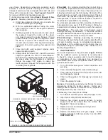
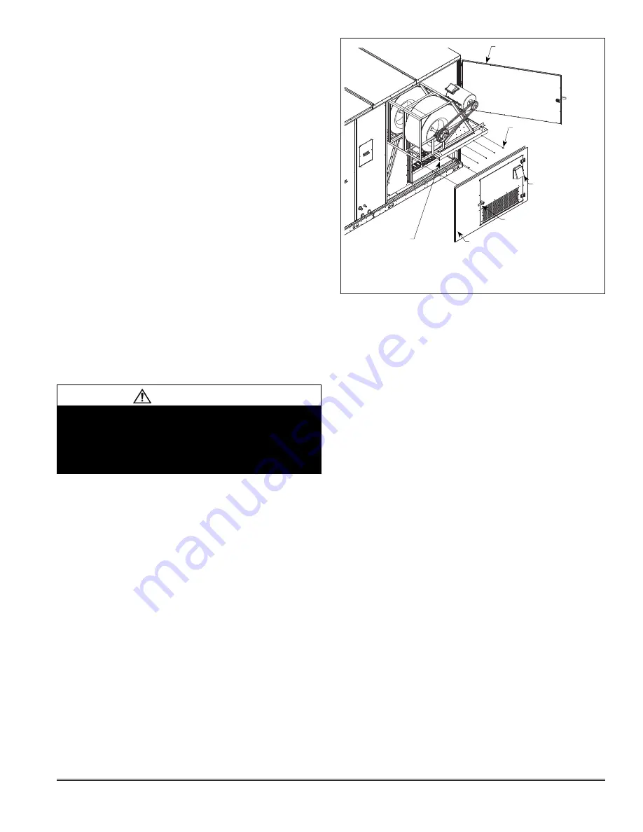
- The dual supply blower assembly in the
EVT-10 and EVT-12 is designed to slide-out for servicing
as shown in
Figure 36
.
Lubrication
- All motors are lubricated at the factory - no
further lubrication is required. Blower shaft bearings are
pre-lubricated; however, for extended bearing life, re-
lubricate at least once every two years with a lithium base
grease, such as Alvania 3 (Shell Oil), Chevron BRB@
(Standard Oil), or Regal AFB2 (Texas Oil).
Use a hand grease gun for re-lubrication and add only
enough grease to purge through the bearings so that a
bead of grease appears at the seal lip contacts.
Under normal operating conditions, the combustion air
inducer wheel should be checked and cleaned prior to
the heating season. However, it should be examined
periodically during the heating season to establish an
ideal cleaning schedule. With power supply disconnected,
the condition of the inducer wheel can be determined by
removing the Flue Vent (
Figure 19
) and looking through
the discharge opening.
Clean the combustion air inducer as follows:
1.
Shut off power supply and gas to unit.
2. Disconnect pressure switch air tubing from combustion
air inducer port.
3.
Remove and retain screws securing flue vent to
the inducer. Remove and retain screws securing
combustion air inducer to the flue box.
See Figure
19.
4. Clean inducer wheel blades with a small brush and
wipe off any dust from housing. Clean accumulated
dust from front of flue box cover.
At this point the flue passageway and flue box may be
cleaned as described below.
5. Reassemble the unit. It is recommended that the
combustion air inducer gasket be replaced during
reassembly.
6. Clean combustion air inlet louvers on heat access
door using a small brush.
WARNING
The State of California has determined that this
product may contain or produce a chemical or
chemicals, in very low doses, which may cause
serious illness or death. It may also cause cancer,
birth defects, or reproductive harm.
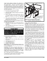
FIGURE 36 - SLIDE-OUT BLOWER ASSEMBLY
BLOWER ACCESS DOOR
REMOVE SCREWS TO SLIDE
BLOWER ASSEMBLY OUT
OF UNIT
FLUE VENT COVER
DISENGAGE HANDLE BEFORE
ATTEMPTING TO REMOVE
STATIONARY PANEL
REMOVE STATIONARY PANEL BEFORE
ATTEMPTING TO SLIDING BLOWER
ASSEMBLY
BLOWER ASSEMBLY
SLIDING BASE
For EVT-10 & EVT-12 Units Only: Blower assembly
slides out to provide rear-blower service access.
Supply / Exhaust Blower Wheels
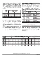
Fan Belts
- Check on a regular basis for wear, tension,
alignment, and dirt accumulation. Premature or frequent
belt failures can be caused by improper belt tension or
misaligned sheaves. Abnormally high belt tension or drive
misalignment will cause excessive bearing loads and may
result in failure of the fan and/or motor bearings. Loose
belts will cause squealing on start-up, excessive belt
flutter, slippage, and overheated sheaves. Both loose
and tight belts can cause fan vibration.
When replacing belts on multiple groove drives, all belts
must be changed in matched sets to provide uniform drive
loading. Do not pry belts on or off the sheave. Loosen
belt tension until belts can be removed by simply lifting
off of the sheave. Belt dressing should never be used.
Never install new belts on worn sheaves. If the sheaves
have grooves worn in them, they must be replaced before
new belts are installed. Determine proper belt tension as
shown in
Figure 17
.
Fan Motors
- All motors use pre-lubricated, sealed
bearings that require no further lubrication. Motor
maintenance is generally limited to inspection and
cleaning. Cleaning should be limited to exterior surfaces
only. Removing dust and grease buildup on motor
housing aids motor cooling. Never wash-down motor with
high pressure spray.
Fan Wheels
- Require little attention when moving clean
air. Occasionally oil and dust may accumulate causing
imbalance. When this occurs the wheel and housing
should be cleaned to assure smooth and safe operation.
Inspect fan wheel and housing for fatigue cracks,
corrosion and wear.
Summary of Contents for ENERVENT+ EVT-09 Series
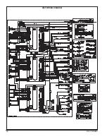
Page 30: ...30 REVT 05ERV UNIT WIRING DIAGRAM ...
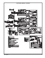
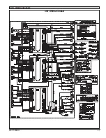
Page 31: ...REVT 05ERV 31 UNIT WIRING DIAGRAM CONTINUED ...
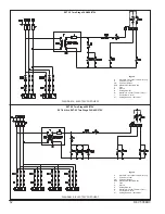
Page 47: ...REVT 05ERV 47 UNIT WIRING DIAGRAM XVIII WIRING DIAGRAMS ...
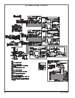
Page 48: ...48 REVT 05ERV UNIT WIRING DIAGRAM CONTINUED ...
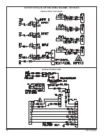
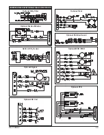
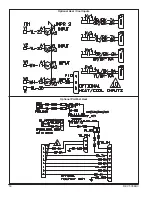
Page 50: ...50 REVT 05ERV Optional Heat Cool Inputs Optional Pre Post Heat ...
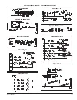
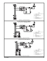
Page 57: ...REVT 05ERV 57 DIAGRAM 15 5 1 MODULATION GAS POST HEAT DIAGRAM 14 2 STAGE GAS POST HEAT ...

