38 REVT-05ERV
XVII - VFD FACTORY SET POINTS
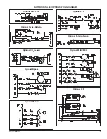
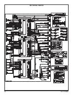
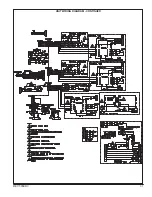
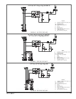
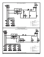
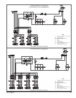
XVIII - WIRING DIAGRAMS, PRE- AND POST-HEAT
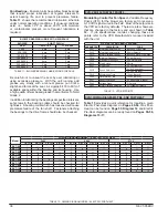
Fan Bearings
- Enervent units have pillow block bearings
that require proper lubrication at regular intervals to
extent bearing life and to prevent premature failure.
Table 11
shows the recommended lubrication schedule
under normal operating conditions. If unusual conditions
exist; i.e., below 32°F or above 200°F, with moisture
or contaminants present, more frequent lubrication is
required.
Be careful not to unseat the seal by over lubricating or
using excessive pressure. With the unit running, add
grease very slowly with a manual grease gun until a
slight bead forms at the seal. As a guide fill 30 to 60% of
available space within the bearing and its housing. Use
a high quality lithium based grease that conforms to NLGI
Grade 2.
In addition to lubricating the bearings at specified intervals,
set screws in the bearing collars should be checked for
tightness. A bearing collar which has loosened will cause
premature failure of the fan shaft. Fasteners attaching
the bearings to the drive frame should also be checked.
BLOWER BEARING LUBRICATION SCHEDULE
BLOWER
SHAFT DIA (in.)
RPM
1.00 to 1.50
1.75 to 2.00
< 500
6 mo
6 mo
500-1000
6 mo
5 mo
1000-1500
5 mo
4 mo
1500-2000
4 mo
3 mo
2000-2500
4mo
2 mo
2500-3000
3 mo
1 mo
3000-3500
2 mo
1 mo
VFD STARTUP WITH BASIC PROGRAM
PARAMETER
DESCRIPTION
CODE
P031
Motor Nameplate Amps
Based on Drive Rating
P032
Motor Nameplate Hertz
60 Hz (Default)
P033
Motor Overload Current
Based on Motor FLA Rating
P034
Minimum Frequency
0.0 Hz (Default)
P035
Maximum Frequency
60.0 Hz (Default)
P036
Start Source
2-Wire
P037
Stop Mode
0-Coast (Default)
P038
Speed Reference
2 = 0-10 Volt Input
3 = 4-20 ma Input
P039
Acceleration Time
10 sec (Default)
P040
Deceleration Time
10 sec (Default)
P041
Reset to Defaults
0 = Ready/Idle (Default)
P042
Voltage Class
3 (Default)
P043
Motor Overload Retention
0 = Disabled (Default)
Model
WIRING DIAGRAM NUMBER -- ELECTRIC POST-HEAT
240V
480V
575V
1-STG
2-STG
3-STG
4-STG
1-STG
2-STG
3-STG
4-STG
1-STG
2-STG
3-STG
4-STG
EVT-09
1
—
—
—
1
—
—
—
1
—
—
—
EVT-19
1
4
—
—
1
4
—
—
1
4
—
—
EVT-28
2
—
—
—
2
—
—
—
2
—
—
—
EVT-36
2
6
—
—
2
5
—
—
2
5
—
—
EVT-46
2
6
—
—
2
5
—
—
2
5
—
—
EVT-62
2
6
8
—
2
5
9
—
2
5
10
—
EVT-74
3
7
—
—
2
6
—
—
2
6
—
—
EVT-88
3
7
11
—
2
6
8
—
2
6
8
—
EVT-10
3
7
11
—
2
6
8
—
2
6
8
—
EVT-12
3
7
11
12
2
6
8
13
2
6
8
13
TABLE 11 - BLOWER BEARING LUBRICATION SCHEDULE
TABLE 12 - VFD SETPOINTS
TABLE 13 - WIRING DIAGRAM INDEX - ELECTRIC POST-HEAT
Modulating Control for Fan Speed
– Variable Frequency
Drives (VFD) for the blower are factory set to receive a
0-10 VDC signal wired in the field. Most of the setpoints in
the VFD’s are factory defaults. There are a few, however,
that are changed in the factory and are shown in
Table
12.
If job specifications requires changing these set
points refer to the VFD Manufacture's manual included
with the unit.
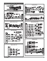
Table 13
provides a quick reference for locating a given
Electric Post-Heat diagram on
Pages 49-54
. Gas Post-
Heat can be found on
Page 55
,
Diagram 14
and Electric
Pre-Heat diagrams can be ready found on
Pages 55-56,
Diagrams 15-17.
Summary of Contents for ENERVENT+ EVT-09 Series
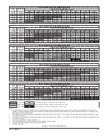
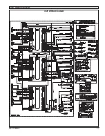
Page 30: ...30 REVT 05ERV UNIT WIRING DIAGRAM ...
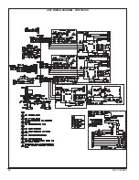
Page 31: ...REVT 05ERV 31 UNIT WIRING DIAGRAM CONTINUED ...
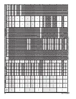
Page 47: ...REVT 05ERV 47 UNIT WIRING DIAGRAM XVIII WIRING DIAGRAMS ...
Page 48: ...48 REVT 05ERV UNIT WIRING DIAGRAM CONTINUED ...
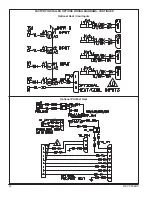
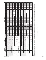
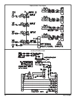
Page 50: ...50 REVT 05ERV Optional Heat Cool Inputs Optional Pre Post Heat ...
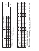
Page 57: ...REVT 05ERV 57 DIAGRAM 15 5 1 MODULATION GAS POST HEAT DIAGRAM 14 2 STAGE GAS POST HEAT ...

