REVT-05ERV 5
B. OPTIONS and ACCESSORIES
14. DAMPERS
- Parallel-blade, motorized or gravity,
damper assembly for outdoor or exhaust airflow.
Aluminum blades with galvanized steel frames.
15. DEFROST CONTROL
- Three types of frost control
available:
a. Electric pre-heater
b. Exhaust only (low ambient kit)
c. Modulating wheel frost control
Pre-Heater
- An ETL Certified Component, two-stage
heater with controls wired at the factory. Single point
power for the heating elements to be field provided.
16. SUPPLEMENTAL POST-HEAT
- Two post-heaters
are available: Gas Fired (shown) and Electric.
Gas Fired Post-Heat
- An ETL Certified Component.
Standard with aluminized inshot burners, direct spark
ignition, electronic flame sensor, combustion air
inducer, and redundant automatic 2-stage (EVT-28
and larger) gas valve with manual shut-off. Additional
options available are 5:1 modulation and; when a high
turn-down gas input ratio is needed; a split-manifold,
10:1 modulation is recommended to optimize
efficiency at the highest rate. Heat exchanger is
tubular construction, aluminized steel (EVT-10 and
EVT-12 are stainless steel), and life cycle tested.
Stainless steel heat exchanger is an option, but
is required if mixed air temperature is below 45°F.
Electric spark ignition of burners on each operating
cycle. System permits main gas valve to stay open
only when the burners are proven to be lit. Should a
loss of flame occur, gas valve closes, shutting of gas
to burners. Ignition module has LED to indicate status
as troubleshooting aid. Ignition control is factory
installed in heating compartment. Redundant limit
controls are factory installed with fixed temperature
setting. Heat limit controls protect heat exchanger
and other components from overheating. Flame roll-
out switch, flame sensor and combustion air inducer
proving switch protect system operation.
Electric Post-Heat
- An ETL Certified Component,
with controls wired at the factory. Single point power
for the heating elements to be field provided. Staging
ranges from 1 to 4 depending on the unit size and
heater option selected.
17. TEMPERING COILS
- Copper tube and aluminum
fin construction, rated in accordance to ARI Standard
410. Tubing and return bends are seamless copper
conforming to ASTM B75 and ASTM B251 for standard
pressure applications. Designed to withstand 250
psi maximum operating pressures and a maximum
temperature of 300°F. Aluminum fins are Sine Wave
and are die-formed to provide self-spacing collars
which completely cover the entire tube surface.
Copper tubes are mechanically expanded to form an
interference fit with the fin collars.
Chilled and Hot Water
- Design permits in-tube
water velocities up to 6 ft/sec. Headers have factory-
installed air vents and drain plugs placed at the highest
and lowest points respectively. MPT connections are
provided.
Direct Expansion
- All copper tubing is internally
enhanced with Rifled surfacing for improved heat
transfer performance. Factory-installed, externally
adjustable, Thermal Expansion Valve is standard.
Two-stage, interlaced circuiting is provided for the
EVT-46 and larger units with the Neutral Air Option
(
See SECTION VI - TEMPERING MODE
) and for the
EVT-28 and larger with the Neutral Air Plus Option.
PRODUCT SPECIFICATIONS
- A summary of
specifications for the
E
series is listed in
Table 14. See Page 39.
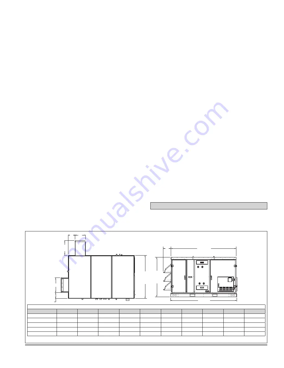
V - DIMENSIONS
Overall unit dimensions are illustrated and tabulated in
Figure 2
.
FIGURE 2 - OVERALL DIMENSIONS
J
H
K
G
F
D
(BASE) B
E
C
A
UNIT OVERALL DIMENSIONS (INCHES)
UNIT
A
B
C
D
E
F
G
H
J
K
EVT-09 / -19
93
1/2
47
3/8
92
1/4
51
3/4
11
1/8
6
5/8
17
3/4
9
14
3/8
18
1/4
EVT-28 / -36
110
7/8
54
3/8
109
5/8
61
5/8
13
7/8
6
3/4
20
8
5/8
15
3/8
18
1/4
EVT-46 / -62
135
1/2
70
134
1/4
79
1/2
17
1/2
7
1/4
24
1/2
11
7/8
20
3/8
18
1/4
EVT-74 / -88
149
1/2
76
7/8
148
90
1/4
19
1/4
11
3/8
29
12
1/4
27
3/4
21
1/4
EVT-10 / -12
161
1/2
88
1/4
160
1/4
101
7/8
21
10
3/4
34
15
3/8
27
3/4
21
1/4
Summary of Contents for ENERVENT+ EVT-09 Series
Page 30: ...30 REVT 05ERV UNIT WIRING DIAGRAM ...
Page 31: ...REVT 05ERV 31 UNIT WIRING DIAGRAM CONTINUED ...
Page 47: ...REVT 05ERV 47 UNIT WIRING DIAGRAM XVIII WIRING DIAGRAMS ...
Page 48: ...48 REVT 05ERV UNIT WIRING DIAGRAM CONTINUED ...
Page 50: ...50 REVT 05ERV Optional Heat Cool Inputs Optional Pre Post Heat ...
Page 57: ...REVT 05ERV 57 DIAGRAM 15 5 1 MODULATION GAS POST HEAT DIAGRAM 14 2 STAGE GAS POST HEAT ...


