


REVT-05ERV 7
1. Turn each blower wheel by hand to ensure it turns
freely and does not bind.
2. Inspect dampers (if supplied) for free operation of all
moving parts.
3. If damage is found, record all necessary information
on the bill of lading and file a claim with the final
carrier.
C. REQUIREMENTS
If the unit is stored for any length of time prior to installation
it must be stored in the original crate and protected from
dust, debris, and weathering. If storage is in a humid,
dusty or corrosive atmosphere, rotate the blowers and
purge the bearings once a month. Improper storage
resulting in damage to the unit or components will void
the warranty.
Use of this unit as a construction heater is not
recommended during any phase of construction. If it has
been used for heating of buildings under construction, the
following conditions must be met or the warranty will be
void:
• The Intake Hood must be installed per these
installation instructions.
• The Flue Vent Hood (gas heat option) must be
installed.
• A room thermostat must control the unit; i.e., the
use of fixed jumpers that will provide continuous
heating is not allowed.
•
Air filters must be replaced upon construction
completion.
• The input rate and temperature rise must be set
per the unit rating plate.
•
The unit operating conditions (including airflow,
ignition, input rate, temperature rise, and venting)
must be verified according to these installation
instructions.
VIII - UNIT PLACEMENT and SUPPORT
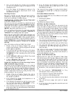
A. POSITIONING (MIN CLEARANCES)
General Unit Requirements
Do not position the unit with the outdoor air intake into the
prevailing wind and keep the intake away from any other
exhaust fans. Likewise, position the exhaust discharge
opening away from the outdoor intakes of other units.
The following items must be completed prior to rigging
and lifting the ERV onto the roof.
WARNING
Electric shock hazard and danger of
explosion. Can cause injury, death
or product or property damage. Turn
off gas and electrical power to unit
before performing any maintenance or
servicing operations on the unit. Follow
lighting instructions attached to unit
when putting unit back into operation
and after service or maintenance.
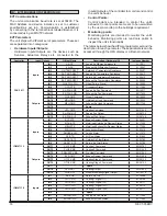
MINIMUM CLEARANCES (INCHES)
UNIT
A
B
C
D
EVT-09/-19
48
36
42
42
EVT-28/-36
48
36
48
42
EVT-46/-62
48
36
60
48
EVT-74/-88
48
42
72
48
EVT-10/-12
48
48
84
48
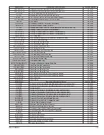
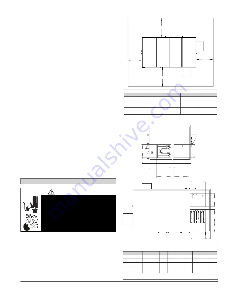
SUPPLY AND RETURN DUCT OPENINGS DIMENSIONS (INCHES)
UNIT
A
B
C
D
E
F
G
H
J
EVT-09/-19
18
16
18
16
3
3/4
6
1/2
11
9
7
EVT-28/-36
22 22
1/8
22
1/8
22
1/8
3
15/16
7
13/16
9
3/4
10 6
5/16
EVT-46/-62
28
28
28
28 4
15/16
8
1/8
13
1/4
13
5/16
7
EVT-74/-88 33
7/8
34
1/8
34
34 4
7/16
12
9/16
11
1/8
12
5/8
6
5/8
EVT-10/-12
34
42
42
34
6
8
5/8
15
3/8
15
7
1/4
A
A
A
F
G
B
B
E
D
E
C
C
H
J
D
B
C
D
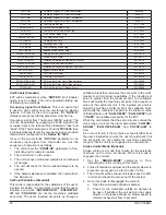
FIGURE 3 - MINIMUM CLEARANCES
FIGURE 4 - DUCT OPENINGS
ALL UNITS WITH GAS POST-HEAT
OPTION - 42 INCH MINIMUM
TO COMBUSTIBLE MATERIAL
Summary of Contents for ENERVENT+ EVT-09 Series
Page 30: ...30 REVT 05ERV UNIT WIRING DIAGRAM ...
Page 31: ...REVT 05ERV 31 UNIT WIRING DIAGRAM CONTINUED ...
Page 47: ...REVT 05ERV 47 UNIT WIRING DIAGRAM XVIII WIRING DIAGRAMS ...
Page 48: ...48 REVT 05ERV UNIT WIRING DIAGRAM CONTINUED ...
Page 50: ...50 REVT 05ERV Optional Heat Cool Inputs Optional Pre Post Heat ...
Page 57: ...REVT 05ERV 57 DIAGRAM 15 5 1 MODULATION GAS POST HEAT DIAGRAM 14 2 STAGE GAS POST HEAT ...


