5
Russound ALTx-2 Installation Manual
Rev. 2
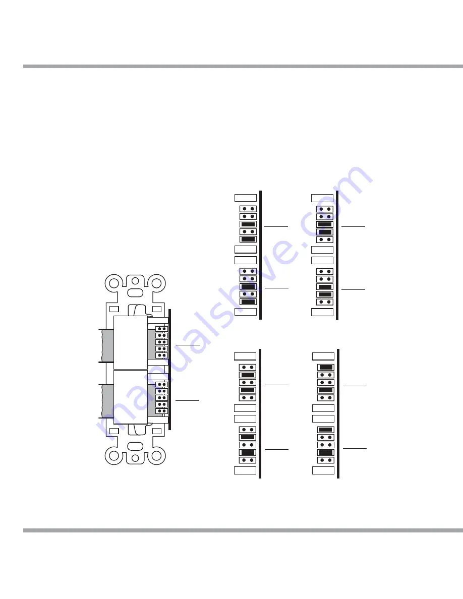
SETTING JUMPERS
Jumper Location and Adjustment
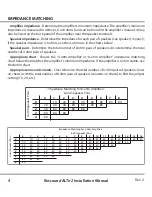
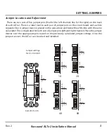
There are two sets of five jumper pins (five for the left channel, five for the right) on the back
of each ALTx-2. There is a label next to each pair of jumper pins on the circuit board, and a white
separator line. A jumper sleeve is placed on the pins above and below the white line with the same
value label. This is duplicated for both sets of jumper pins (left and right channel). Place the jumper
sleeves over the appropriate pins based on the previously calculated jumper settings. Once the
jumpers are set, the ALTx-2 can be wired and installed.
8X
4X
1X
2X-4X-8X
1X-2X
8X
4X
1X
2X-4X-8X
1X-2X
1X
8X
4X
1X
2X-4X-8X
1X-2X
8X
4X
1X
2X-4X-8X
1X-2X
8X
4X
1X
2X-4X-8X
1X-2X
8X
4X
1X
2X-4X-8X
1X-2X
8X
4X
1X
2X-4X-8X
1X-2X
8X
4X
1X
2X-4X-8X
1X-2X
8X
4X
1X
2X-4X-8X
1X-2X
8X
4X
1X
2X-4X-8X
1X-2X
Back of ALTx-2/2D
Jumper settings
for 1X, 2X, 4X, 8X
2X
4X
8X

