DMS-3.1 Test Procedure
40
of
64
Turn on DMS-3.1
1. Turn on the MCA-C5 if it is not already on.
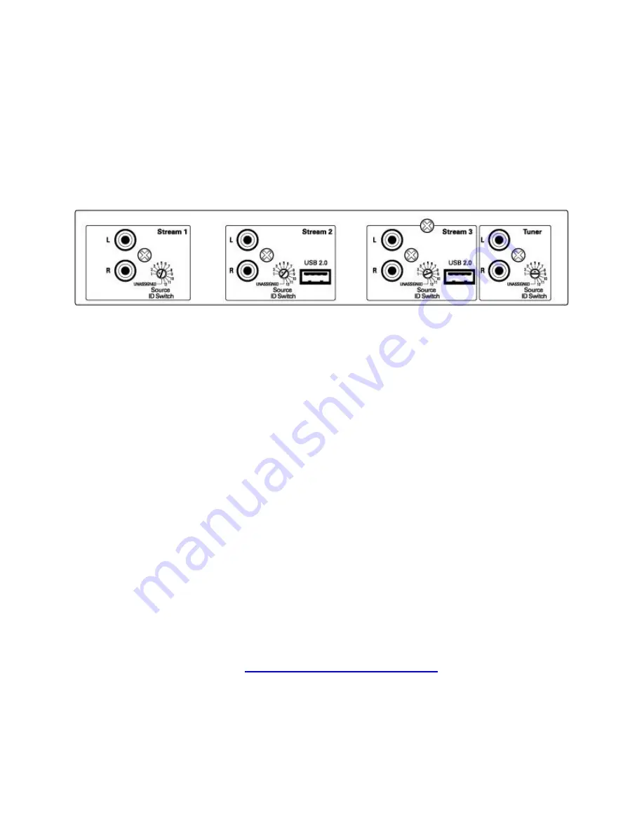
Check the DMS-3.1 ID Switches were set to the following:
Stream 1 ID Switch to Position 2
Stream 2 ID Switch to Position 3
Stream 3 ID Switch to Position 4
Tuner ID Switch to Position 5
2. Turn on the DMS-3.1 Streamer.
About 10 Seconds later the Link and Traffic LED’s will illuminate on the Ethernet
Jack located on the rear of the DMS-3.1. Check they are both illuminated.
Left LED is green, Right LED is yellow.
Check the “Red” Front Panel LED under the power switch is illuminated.
3. Step 3 and 4 are optional but will help in determining a problem if a Stream
is not working.
There are six LED’s on the PCB.
D14, D4, and D6 are Red LED’s.
D13, D3, and D5 are Green LED’s.
About the same time the Ethernet Link and Traffic LED’s illuminate,
The 3 Red LED’s will Blink momentarily, then
The 3 Green LED’s will Blink momentarily, then
All six LED’s will be dark.
Looking from the Rear of the DMS-3.1 you can look through the vent holes of the
cover and view the six LED’s. Look at the vent holes on the Left side.
4. After a few more seconds all six LED’s in Step 3 will illuminate indicating each
BridgeCo module is talking to the network via the switch U3 on the PCB.
5. After approximately two minutes the DMS-3.1 has booted up.
6. Continue by performing the
“IP Address & DMS-3.1 MAC ID”
section.
Summary of Contents for DMS-3.1
Page 1: ......
Page 27: ...SMS_USB_ _PWR_LED_Front_RevA_7_19_10 sch 1 Wed Jul 28 15 07 39 2010 ...
Page 116: ......


