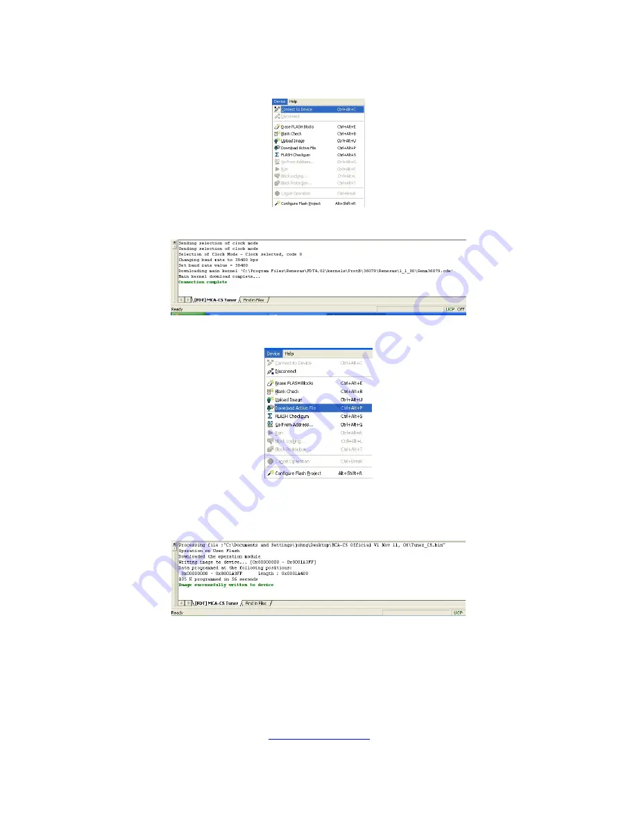
11. Click “Device” then “Connect to Device”.
12. The bottom window will display Connection Complete.
13. Click “Device” then “Download Active File” menu.
14. You will observe a progress bar at the bottom of the FDT 4.01 window.
The bottom window will display in green when the Tuner has been
successfully programmed.
15. Close FDT 4.01.
16. Turn off the MCA-C5.
17. Unplug the Advanced Programming cable from J11 of the DIO PCB.
18. Connect a two pin jumper to J12 pins 1 and 2 on the Digital I/O PCB.
Pin 1 has the square pad on the pcb.
19. Install the DIO PCB into the MCA-C5 chassis.
20. Install cover.
21. Continue by performing the
section.
MCA-C5 Test Procedure
Rev 1.5
Page 24 of 78
Summary of Contents for MCA-C5
Page 1: ......
Page 41: ...39 Russound MCA C5 User and Installation Manual Notes ...
Page 166: ...ZXP E5 Power Supply_RevC sch 1 Thu Dec 18 16 48 45 2008 C ...
Page 167: ...ZXP E5 Power Supply_RevC sch 2 Thu Dec 18 16 48 46 2008 ...
Page 168: ...ZXP E5 Power Supply_RevC sch 3 Thu Dec 18 16 48 46 2008 ...
Page 189: ......


