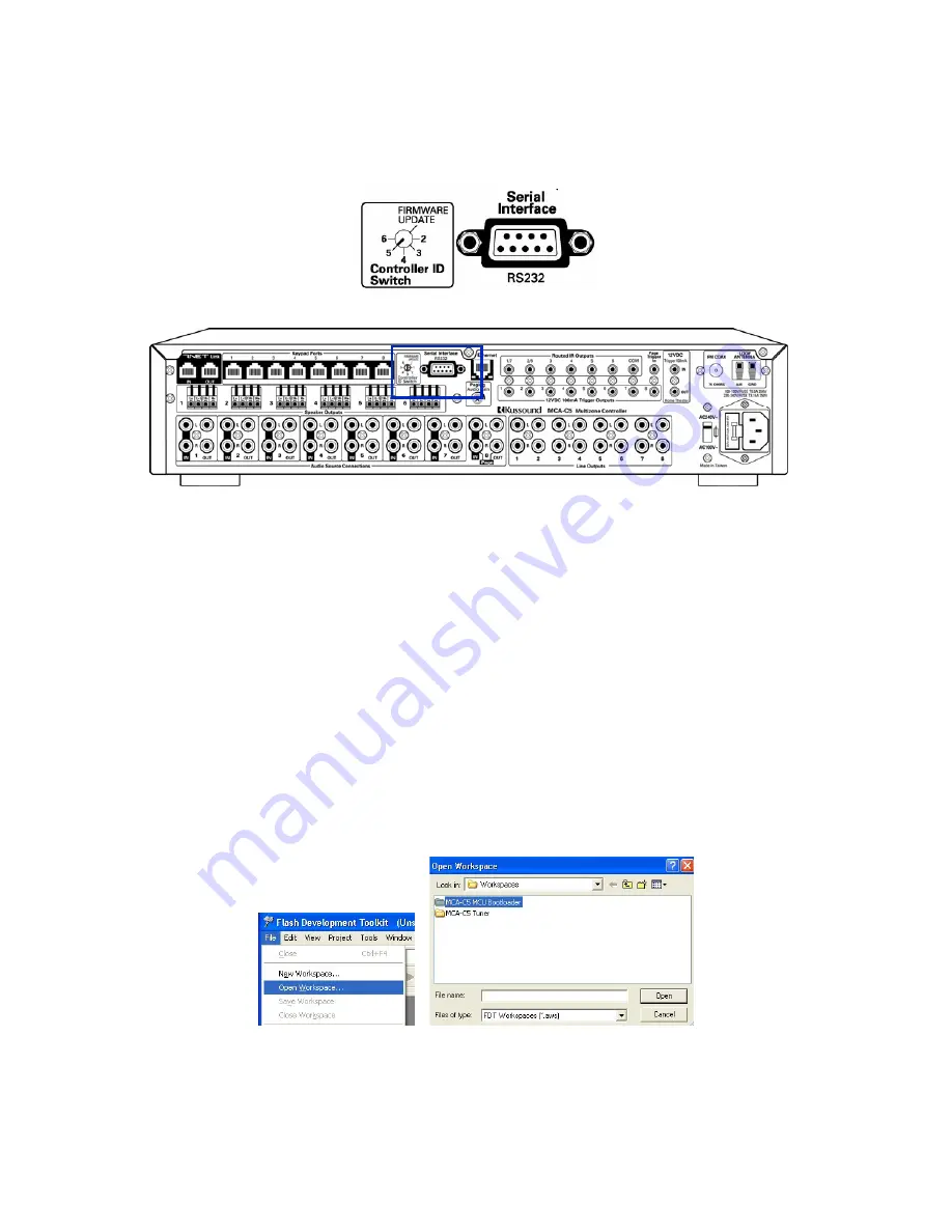
Firmware/Bootloader Programming
1. Move the Controller ID Switch to the Firmware Update position.
2. Connect the computer’s RS232 cable to the Serial Interface RS232A Port
of the
MCA-C5
.
Note: If a DB9 switch is used, like the one used in the “Initial Test Setup”
section, select the MCA-C5 position of the DB9 Switch.
3. Set the AC240V~ / AC100V~ switch to AC100V~.
4. Plug the
MCA-C5
into an 110V AC Outlet.
5. Press the power button on the front panel to turn on the
MCA-C5
.
6. Open FDT 4.01.
7. Click “File” then “Open Workspace”.
Select and Open the “MCA-C5 Boot Loader”.
Select and Open the “MCA-C5 Boot Loader.AWS” file.
Note: If the MCA-C5 Boot Loader is in the left hand window
(Projects pane) you can continue to the next step.
MCA-C5 Test Procedure
Rev 1.5
Page 19 of 78
Summary of Contents for MCA-C5
Page 1: ......
Page 41: ...39 Russound MCA C5 User and Installation Manual Notes ...
Page 166: ...ZXP E5 Power Supply_RevC sch 1 Thu Dec 18 16 48 45 2008 C ...
Page 167: ...ZXP E5 Power Supply_RevC sch 2 Thu Dec 18 16 48 46 2008 ...
Page 168: ...ZXP E5 Power Supply_RevC sch 3 Thu Dec 18 16 48 46 2008 ...
Page 189: ......


