background image

R H

• • • • • • • • • • • • • • • • • • • • • • • • • • • • • • • • • • • • • • • • •

I N S T A L L A T I O N   I N S T R U C T I O N S

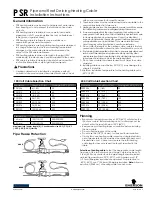
1. Measuring and Marking the Header

•  Measure and pencil a line 1-3/4” up from the 

  bottom of the Header. You will align this line 

  with the line on your wall.

3. Marking Drill Holes to Attach Bracket

•  Place a Bypass Bracket centered onto the first vertical 

  pencil marking, with the bottom of the Bracket Edge

  touching the bottom horizontal penciled line (1” 

  from bottom edge of Header). 

•  With a pencil, mark the center of each of the four 

  holes in the Bracket back. Repeat for remaining Brackets.

Header and Brackets

Page 7

1-3/4”

•  Lay the Track along the line, centering 

  the Track holes over the line. 

•  Mark the center of each of the holes 

  with a vertical line. 

2. a. Marking Bracket Locations

2. b. Marking Bracket Locations

Marked and ready to drill pilot holes.

•  Measure and pencil a second line 1” up from the 

  bottom of the Header. This is where you will 

  align the bottom edges of the Brackets.

1”

Summary of Contents for Heavy-Duty Bypass Track System

Page 1: ... T A L L A T I O N I N S T R U C T I O N S RH040 1 28 2015 Please Note This track system must be installed with the screws going into a solid surface such as studs or a header Due to the spacing of the holes on these Brackets it is not possible to mount them directly onto your wall into studs ...

Page 2: ...R H I N S T A L L A T I O N I N S T R U C T I O N S Bypass Brackets Bypass Splice Plate Bracket For splicing two or more Tracks together Brackets Page 2 4 3 4 3 1 2 4 1 8 2 1 4 6 3 8 ...

Page 3: ...ag Bolts 1 Washers Door Guide Tools Needed Parts Included Track Stops Lag Screws Track Splice Plate Bracket included when two or more tracks are needed Wall Mount Door Guide optional Parts and Tools Page 3 Open Hex Nuts PLEASE NOTE These instructions are specific to a particular Track System Adjustments may be needed on your part for changes in specifications and mea surements as well as Track Sys...

Page 4: ...unt Door Guide as a Come Along will allow open ing and closing both Doors with one easy motion See pages 11 and 12 Two Door Setup Four Door Setup Door Setups Page 4 Please Note This track system must be installed with the screws going into a solid surface such as studs or a header Due to the spacing of the holes on these Brackets it is not possible to mount them directly onto your wall into studs ...

Page 5: ... All four Doors glide smoothly out of the way two to one side and two to the other side Installing a Wall Mount Door Guide as a Come Along on each pair will allow open ing and closing your Doors on either side with one easy motion see pages 11 and 12 Door Setups Page 5 ...

Page 6: ...long the length of the Track you risk your Door rubbing or sticking at this high point If your floor is not level determine where the highest point of your floor is and use this as your point to measure from upwards see Step 2 1 If Your Finished Floor is Not Level Check to see if your floor is level within this area below your track Track Location Page 6 of inches up from finished floor where you ...

Page 7: ... the bottom horizontal penciled line 1 from bottom edge of Header With a pencil mark the center of each of the four holes in the Bracket back Repeat for remaining Brackets Header and Brackets Page 7 1 3 4 Lay theTrack along the line centering the Track holes over the line Mark the center of each of the holes with a vertical line 2 a Marking Bracket Locations 2 b Marking Bracket Locations Marked an...

Page 8: ...ur for each Bracket Attach each Bracket with Lag Screws and a Ratchet 3 Attach Brackets to Header 2 Attach Header to Wall Align the top penciled line on your Header 1 3 4 from the bottom of the Header with the penciled line on your wall Use a level to ensure your Header is straight Attach the Header to the wall making sure you are drilling and attaching into wall studs Page 8 9 16 ...

Page 9: ...talled in this order Track Washer and Lag Bolt Using a ratchet with a 5 8 socket tighten the Lag Bolt most of the way Install remaining inside holes in the same order When all holes are installed go back with a ratchet with a 5 8 socket and fully tighten being careful not to over tighten to avoid stripping the header or wall studs 2 Hanging Your Back Door s Installing Tracks If more that one lengt...

Page 10: ...th a Phillips bit install a 1 Grabber Screw to secure your Door Guide to the floor _____________________ Plumb perfectly vertical With a Bypass Track System either a Wall Mount or a Floor Mount Door Guide can be installed on the back Door the one that is closest to the wall An additional Wall Mount Door Guide can be installed onto the front of the back door connecting to the front Door and acting ...

Page 11: ...With the edge of the Bracket back lined up with the line you just penciled shift the Bracket up slightly so the vertical Bracket edge is inside the mortised groove holding the door in place yet the mortised groove clears the top of the Bracket edge With a Phillips drill bit drill a Grabber Screw into each hole in the Bracket back plate Slide front Door so the mortise along the bottom of the Door s...

Page 12: ...nd Plates The mortise along the bottom of the front Door glides over to cover the vertical Bracket edge 1 Position one of the End Plates over the bottom edge of the front Door aligning the bottom of the Bracket with the Bottom of your Door 2 Using your drill with a Phillips bit drill a Grabber Screw into each of the two holes in the End Plate Attach the other End Plate on the opposite edge of this...

Reviews: