Use teamwork. We recommend two people for this build.
FIRST THINGS FIRST
Check to see if the floor below the track area is level. If the floor rises mor
e than 1/2” the door may rub or not slide
XFMM
If the floor is
not level, measur
e from the highest point o
f the floor surfac
e to the
NBLFTVSFUIFEPPSDMFBSTUIFGMPPS
Ensure the track will be installed onto wall studs or in wall blocking. If wall studs are not lining up with the installation a header will be
required to provide the necessary strength and stability for the track and door.
Figure 2
1.
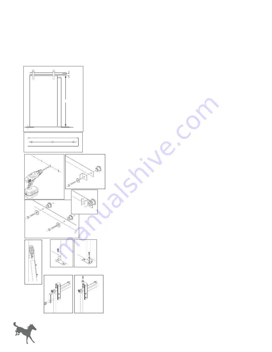
To determine where the track should be installed,
first measur
e
the
height of the door, then add
2-
1/8” to the door
height
. 1/2”
(a)
will be for the
clearance between
the bottom edge of the door
and the floor
. 1-5/8”
(b)
will be from
the top edge of
the door to
the center of the track. (Figure 1).
2.
Using a level and a pencil, make a line
on the wall at this height.
It
will be the centerline of the track.
3.
Hold the track up to where the pencil line is visible
through the
holes in the track (Figure 2).
4.
Mark an intersecting line in the center of each hole
(Figure 2).
5.
Take the track down,
d
rill out the marked holes using a drill with a
1/4” drill bit (Figure 3).
6.
Attach one end of the track to the wall with one
standard
stop,
one lag
screw, and one washer
,
using a socket wrench with 9/16”
socket (Figure 4). Do not tighten.
7.
Repeat step 7 for the other end of the track.
8.
Attach the
rubber bumper
to the inside of the standard
stop.
Repeat for the hard stop on the other end of the track (Figure
4a
).
9.
Install remaining spacers with lag screws and washers
using a
9/16” socket wrench (Figure 5). Tighten all lag screws.
10.
Hang the door (Figure 6).
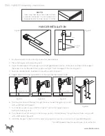
DOOR GUIDE INSTALLATION
11.
With the door in the closed position, ensure the door is hanging
straight using a bubble level.
12.
Position the Door Guide part way into the groove in the bottom
of
the door (Figure 7).
13.
Install the Door Guide using a 1” phillips screw
(provided) and a drill with a phillips bit.
14.
Slide the door toward the open position until the other side of the
Door Guide is exposed.
15.
Install the second 1” phillips screw (provided) using a drill with a
phillips bit (Figure 8).
ANTI-JUMP GUIDE INSTALLATION
16.
Place the Anti-Jump bracket on the door side, moving the
bracket
up until it is between 1/8” and 1/16” from the bottom
edge of the
rail. Mark the placement with a pencil.*
17.
Install the bracket to the door edge with 2 phillips screws
(provided) using a drill with a phillips bit
(Figure 9).
18.
Repeat steps 17 and 18 for the opposite end of the door.
19.
Place the Anti-Jump block on the top of the door (Figure 10).
Using a drill with a phllips bit, install the the block with the 1”
phillips screw (provided).
20.
Repeat steps 20 for the opposite end of the door.
1-5/8”
b
1/2”
a
Door
Height
Figure 3
Figure 1
Figure 4
Figure 5
Figure
4
a
Figure 6
Figure 7
Figure 8
Figure 10
Figure 9
FLAT TRACK
"TTFNCMZ*OTUSVDUJPOT
4
www.Rustica.com


