Installation
Installation
Erhalten Sie die Verdrillung der Paare
sowie die Schirmfolie so lang wie möglich
(bis zur Klemme)!
Beachten Sie die gleiche Belegung nach
Farbcode im Patchpanel und an der jewei-
ligen Anschlussdose.
Drücken Sie die Adern mit dem LSA-Anlegewerk-
zeug AW2 (Artikelnummer 392 000 00) in die
Klemmen (Adern werden gleichzeitig gekürzt).
Entfernen Sie die abgeschnittenen Enden von der
Grundplatte, um Kurzschlüsse zu vermeiden.
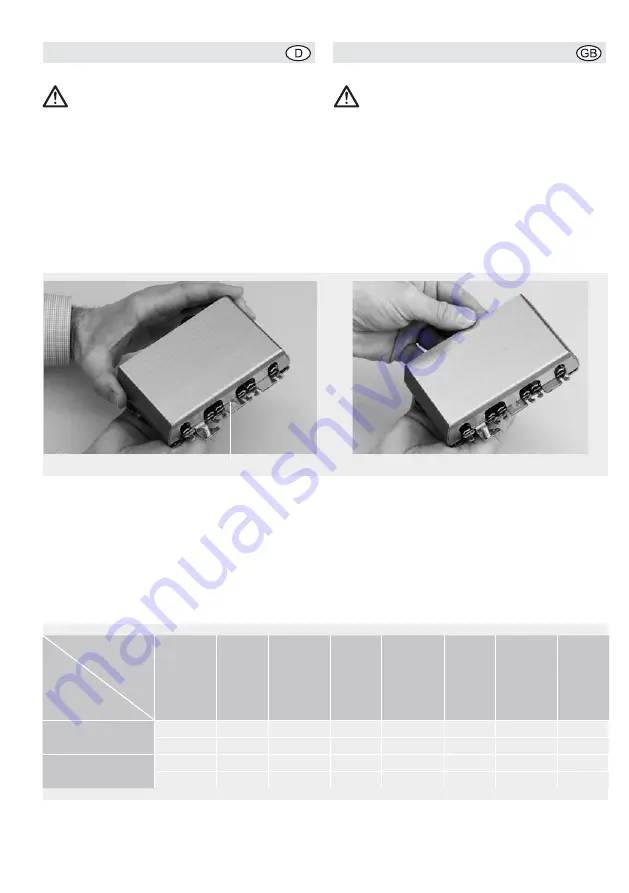
Nach Anschluss der Datenkabel setzen Sie den
Gehäusedeckel beginnend mit der Zentrierhilfe (7)
unmittelbar hinter der Rastnase (3) auf.
Drücken Sie den Gehäusedeckel dann herunter
und schieben Ihnen nach vorn zu, bis er hörbar
einrastet.
Farbcode
Andere Farbkennzeichnungen nach Angaben der
Kabelhersteller möglich.
Keep as much of the braiding and the
shielding foil intact as possible (up to the
terminal)!
Make sure the wires in the patch panel
and on the corresponding jack are con-
nected correctly and according to the
color code..
Press the wires into the terminals (the wires are
simultaneously cut) using the LSA insertion tool AW2
(article number 392 000 00). Remove the cut ends
from the base plate in order to avoid short circuits.
After connecting the data cable, replace the
enclosure cover starting with the centering aid (7)
directly behind the retaining tab (3).
Press the enclosure cover down and push it
towards the front until you hear it click in place.
Color Code
Other color codes may be specified by the cable
manufacturer.
3
7
Anschlussklemme/
Terminal Block
Code
gemäß/acc. to
TIA/EIA-568-B.2
1
2
3
4
5
6
7
8
T568A
weiß/grün
grün
weiß/orange
blau
weiß/blau
orange
weiß/braun
braun
white/green
green
white/orange
blue
white/blue
orange
white/brown
brown
T568B
weiß/orange
orange
weiß/grün
blau
weiß/blau
grün
weiß/braun
braun
white/orange
orange
white/green
blue
white/blue
green
white/brown
brown


