10
INSTALLATION
Replacement Units
To prevent failure of a new unit, the existing line set
must be correctly sized and cleaned or replaced�
Care must be exercised that the expansion device
is not plugged� For new and replacement units, a
liquid line filter drier must be installed and refrigerant
tubing must be properly sized� Test the oil for acid� If
positive, a suction line filter drier is mandatory�
IMPORTANT:
When replacing an
R-22 unit with an R-410A unit, either replace
the line set or ensure that the existing line set is
thoroughly flushed of any old oil or debris� Flush
kits are available through aftermarket HVAC stores
such as Prostock�
Indoor Coil
CAUTION:
Only use evaporators
approved for use on R-410A systems that are
specifically matched with the outdoor unit per
the manufacturer’s specification sheets� Use
of existing R-22 evaporators can introduce
mineral oil to the R-410A refrigerant, forming two
different liquids and decreasing oil return to the
compressor� This can result in compressor failure�
REFER TO INDOOR COIL MANUFACTURER’S
INSTALLATION INSTRUCTIONS.
IMPORTANT:
The manufacturer is not
responsible for the performance and operation of
a mismatched system or for a match listed with
another manufacturer’s coil�
NOTICE:
All (-)PRL units must be
installed with a matched TXV indoor coil� Refer to
manufacturer’s outdoor unit specification sheet for
approved indoor coils�
The thermostatic expansion valve in the
matching coil is specifically designed to operate
with R-410A�
DO NOT use an R-22 TXV or
evaporator� The existing evaporator must
be replaced with the factory-specified TXV
evaporator specifically designed for R-410A�
Location
Do not install the indoor coil in the return duct
system of a gas or oil furnace� Provide a service
inlet to the coil for inspection and cleaning� Keep
the coil pitched toward the drain connection�
CAUTION:
When coil is installed
over a finished ceiling and/or living area, it is
required that a secondary condensate pan be
installed under entire unit� Failure to do so can
result in property damage�
Interconnecting Tubing
All units are factory-charged with R-410A
refrigerant to cover 15 feet of line set� Adjustment
of charge may be necessary even if the application
has exactly 15 feet of line due to other installation
variables and conditions� All models are supplied
with service valves� Keep tube ends sealed until
connection is to be made to prevent system
contamination�
Vapor and Liquid Lines
Keep all lines sealed until connection is made�
Make connections at the indoor coil first�
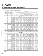
Refer to line size information in the tables on page
12 for correct size and multipliers to be used to
determine capacity for various vapor line diameters
and lengths of run� The losses due to the lines
being exposed to outdoor conditions are not
included�
The factory refrigeration charge in the outdoor
unit is sufficient for the unit and 15 feet [4.6 m]
of standard size interconnecting liquid and vapor
lines without a filter drier� For different lengths,
adjust the charge as indicated below�
1/4" ± .3 oz./foot [6.4 mm ± 8.5 g/.30 m]
5/16" ± .4 oz./foot [7.9 mm ± 11.3 g/.30 m]
3/8" ± .6 oz./foot [9.5 mm ± 17.0 g/.30 m]
1/2" ± 1.2 oz./foot [12.7 mm ± 34.0 g/.30 m]
Add 6 oz� for field-installed filter drier�
Maximum Length of Lines
The maximum length of interconnecting line is
150 feet [45.7 m]. Always use the shortest length
possible with a minimum number of bends�
Additional compressor oil is not required for any
length up to 150 feet [45.7 m].
NOTICE:
Excessively long refrigerant
lines cause loss of equipment capacity�
Tubing
Summary of Contents for ANL-AZ 13 SEER Series
Page 12: ...12 INSTALLATION Interconnecting Tubing cont Tubing...
Page 13: ...13 INSTALLATION Interconnecting Tubing cont Tubing...
Page 14: ...14 INSTALLATION Interconnecting Tubing cont Tubing...
Page 35: ...35 For Single Phase Models WIRING DIAGRAMS Wiring Diagrams...
Page 36: ...36 WIRING DIAGRAMS For Three Phase Models Wiring Diagrams...
Page 37: ...37 Wiring Diagrams APM 018 WITH ECM FAN MOTOR WIRING DIAGRAMS...
Page 38: ...38 NOTES...
Page 39: ...39 NOTES...
Page 40: ...40 NOTES...


