15
INSTALLATION
Interconnecting Tubing (cont�)
Tubing Installation
Observe the following when installing correctly
sized type “L” refrigerant tubing between the
condensing unit and evaporator coil:
• Check the tables on page 12 for the correct
suction line size and liquid line size�
• If a portion of the liquid line passes through a
very hot area where liquid refrigerant can be
heated to form vapor, insulating the liquid line is
required�
• Use clean, dehydrated, sealed refrigeration-
grade tubing�
• Always keep tubing sealed until tubing is in place
and connections are to be made�
• A high-quality biflow filter drier is included
with all R-410A heat pump units and must be
installed in the liquid line upon unit installation�
• When replacing an R-22 system with an R-410A
system and the line set is not replaced, use a
flush kit available through aftermarket stores
such as Prostock�
• If tubing has been cut, make sure ends are
deburred while holding in a position to prevent
chips from falling into tubing� Burrs such as
those caused by tubing cutters can affect
performance dramatically, particularly on small
liquid line sizes�
• For best operation, keep tubing run as short as
possible with a minimum number of elbows or
bends�
• Locations where the tubing will be exposed to
mechanical damage should be avoided� If it is
necessary to use such locations, the copper
tubing should be housed to prevent damage�
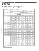
VAPOR LINE CAPACITY MULTIPLIER (PERFORMANCE PENALTY)
NOTES:
1� Using suction line larger than shown in chart will result in poor oil return and is not recommended�
2� Do NOT exceed the limits in the liquid and vapor line-sizing charts�
3� Do NOT use 7/8” OD vapor lines in 1-1/2 or 2-ton applications or 1 1/8” OD vapor lines for any applications�
UNIT SIZE
Suction Line
Connection Size
1
1
⁄
2
Ton
2 Ton
2
1
⁄
2
Ton
3 Ton
3
1
⁄
2
Ton
4 Ton
5 Ton
Suction Line
Run - Feet [m]
5/8" [15.9]
3/4" [19]
*
—
Optional
Standard
Optional
Optional
Standard
Optional
Optional
Standard
Optional
Optional
Standard
Optional
25’
[7.6]
50’
[15.24]
100’
[30.5]
150’
[45.7]
5/8" [15.9]
3/4" [19]
*
—
5/8" [15.9]
3/4" [19]*
7/8
—
3/4" [19]*
—
3/4" [19]
7/8" [22.2]*
—
—
7/8" [22.2]*
—
—
7/8" [22.2]*
—
[ ] Designates Metric Conversions
1.00
1.00
1.00
—
1.00
—
—
1.00
1.00
1.00
1.00
1.00
1.00
1.00
—
—
1.00
1.00
—
1.00
1.00
0.98
0.98
0.96
—
0.99
—
—
0.99
0.99
0.98
0.98
0.99
0.99
0.99
—
—
0.99
0.99
—
0.99
0.99
0.95
0.95
0.94
—
0.96
—
—
0.96
0.96
0.96
0.96
0.98
0.96
0.97
—
—
0.97
0.97
—
0.98
0.98
0.92
0.92
0.91
—
0.94
—
—
0.93
0.94
0.93
0.94
0.96
0.95
0.94
—
—
0.95
0.95
—
0.96
0.97
5/8" [15.9] I.D.
5/8" [15.9] I.D.
3/4" [19] I.D.
3/4" [19] I.D.
7/8" [22.2] I.D.
7/8" [22.2] I.D.
7/8" [22.2] I.D.
Tubing
Summary of Contents for ANL-AZ 13 SEER Series
Page 12: ...12 INSTALLATION Interconnecting Tubing cont Tubing...
Page 13: ...13 INSTALLATION Interconnecting Tubing cont Tubing...
Page 14: ...14 INSTALLATION Interconnecting Tubing cont Tubing...
Page 35: ...35 For Single Phase Models WIRING DIAGRAMS Wiring Diagrams...
Page 36: ...36 WIRING DIAGRAMS For Three Phase Models Wiring Diagrams...
Page 37: ...37 Wiring Diagrams APM 018 WITH ECM FAN MOTOR WIRING DIAGRAMS...
Page 38: ...38 NOTES...
Page 39: ...39 NOTES...
Page 40: ...40 NOTES...


