17
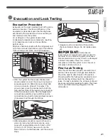
• Braze the tubing between the outdoor unit and
indoor coil� Flow dry nitrogen into a pressure port
and through the tubing while brazing, but do not
allow pressure inside tubing which can result in
leaks� Once the system is full of nitrogen, the
nitrogen regulator should be turned off to avoid
pressuring the system�
• After brazing, use an appropriate heatsink material
to cool the joint�
• Reinstall the Schrader cores into both pressure
ports�
• Do not allow the vapor line and liquid line to
be in contact with each other� This causes an
undesirable heat transfer resulting in capacity
loss and increased power consumption�
Leak Testing
Indoor coils have only a holding charge of dry
nitrogen� Keep all tube ends sealed until
connections are to be made�
WARNING:
Do not use oxygen
to purge lines or pressurize system for leak test�
Oxygen reacts violently with oil, which can cause
an explosion resulting in severe personal injury or
death�
• Pressurize line set and coil through service fittings
with dry nitrogen to 150 PSIG maximum� Close
nitrogen tank valve, let system sit for at least
15 minutes, and check to see if the pressure has
dropped� If the pressure has dropped, check for
leaks at the line set braze joints with soap bubbles
and repair leak as necessary� Repeat pressure
test� If line set and coil hold pressure, proceed
with line set and coil evacuation (see page 21)�
• The vapor line must be insulated for its entire
length to prevent dripping (sweating) and prevent
performance losses� Closed-cell foam insulation
such as Armaflex and Rubatex
®
are satisfactory
insulations for this purpose. Use 1/2" [12.7 mm]
minimum insulation thickness� Additional
insulation may be required for long runs�
INSTALLATION
Interconnecting Tubing (cont�)
Tubing
Summary of Contents for ANL-AZ 13 SEER Series
Page 12: ...12 INSTALLATION Interconnecting Tubing cont Tubing...
Page 13: ...13 INSTALLATION Interconnecting Tubing cont Tubing...
Page 14: ...14 INSTALLATION Interconnecting Tubing cont Tubing...
Page 35: ...35 For Single Phase Models WIRING DIAGRAMS Wiring Diagrams...
Page 36: ...36 WIRING DIAGRAMS For Three Phase Models Wiring Diagrams...
Page 37: ...37 Wiring Diagrams APM 018 WITH ECM FAN MOTOR WIRING DIAGRAMS...
Page 38: ...38 NOTES...
Page 39: ...39 NOTES...
Page 40: ...40 NOTES...


