21
START-UP
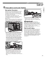
Evacuation Procedure
Evacuation is the most important part of the entire
service procedure� The life and efficiency of the
equipment is dependent upon the thoroughness
exercised by the serviceman when evacuating air
and moisture from the system�
Air or nitrogen in the system causes high
condensing temperatures and pressure, resulting
in increased power input and nonverifiable
performance�
Moisture chemically reacts with the refrigerant and
oil to form corrosive hydrofluoric acid� This attacks
motor windings and parts, causing breakdown�
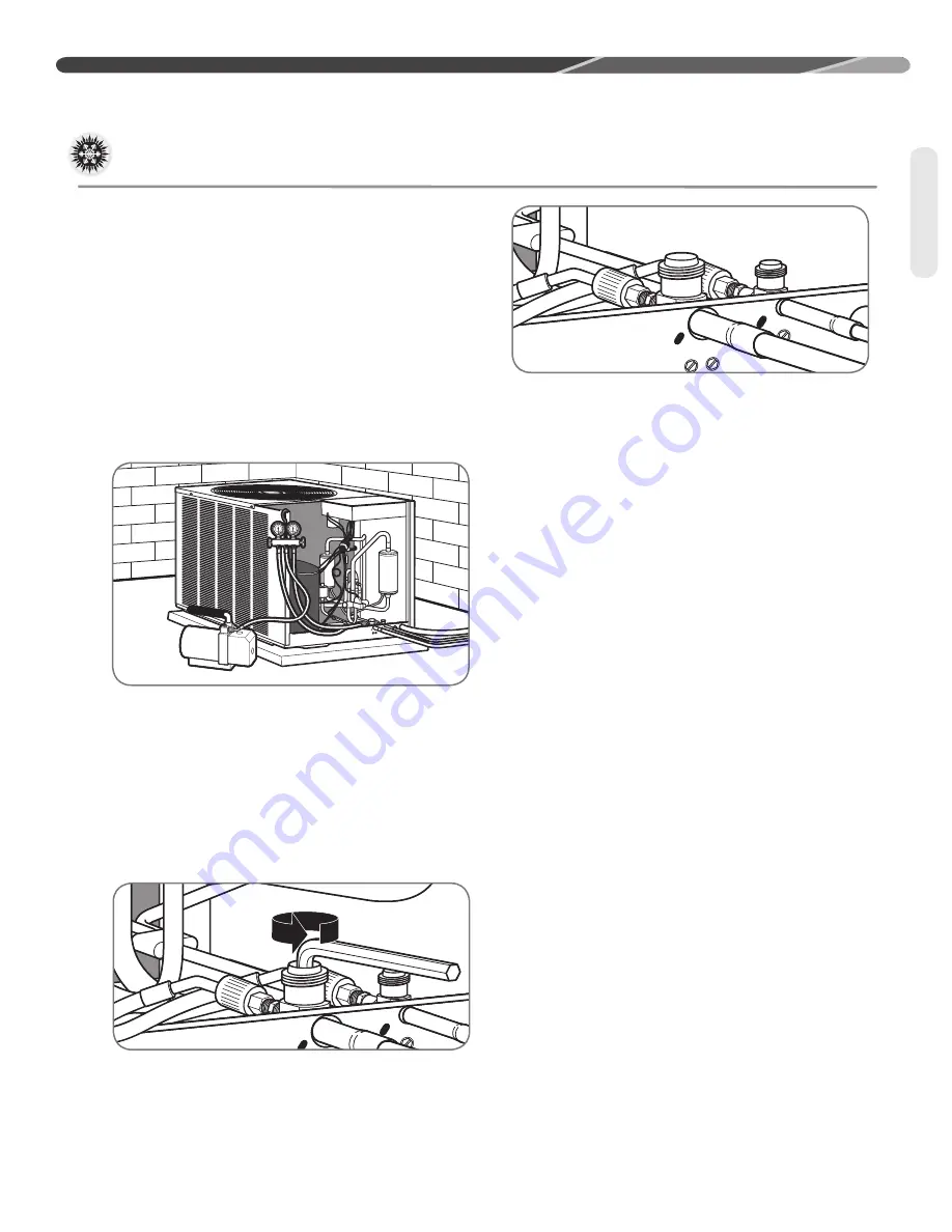
• After the system has been leak-checked and
proven sealed, connect the vacuum pump and
evacuate system to 500 microns and hold 500
microns or less for at least 15 minutes� The
vacuum pump must be connected to both the
high and low sides of the system by connecting
to the two pressure ports� Use the largest size
connections available since restrictive service
connections may lead to false readings because
of pressure drop through the fittings�
• After adequate evacuation, open both service
valves by removing both brass service valve
caps with an adjustable wrench. Insert a 3/16"
[5 mm] or 5/16" [8 mm] hex wrench into the
stem and turn counterclockwise until the wrench
stops�
• Gauges must be connected at this point to
check and adjust charge� Do not replace caps
yet�
IMPORTANT:
Compressors
(especially scroll type) should never be used to
evacuate the air conditioning system because
internal electrical arcing may result in a damaged
or failed compressor� Never run a scroll
compressor while the system is in a vacuum or
compressor failure will occur�
Final Leak Testing
After the unit has been properly evacuated and
service valves opened, a halogen leak detector
should be used to detect leaks in the system�
All piping within the heat pump, evaporator, and
interconnecting tubing should be checked for
leaks� If a leak is detected, the refrigerant should
be recovered before repairing the leak� The Clean
Air Act prohibits releasing refrigerant into the
atmosphere�
Evacuation and Leak Testing
Evacuation
Summary of Contents for ANL-AZ 13 SEER Series
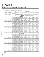
Page 12: ...12 INSTALLATION Interconnecting Tubing cont Tubing...
Page 13: ...13 INSTALLATION Interconnecting Tubing cont Tubing...
Page 14: ...14 INSTALLATION Interconnecting Tubing cont Tubing...
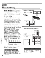
Page 35: ...35 For Single Phase Models WIRING DIAGRAMS Wiring Diagrams...
Page 36: ...36 WIRING DIAGRAMS For Three Phase Models Wiring Diagrams...
Page 37: ...37 Wiring Diagrams APM 018 WITH ECM FAN MOTOR WIRING DIAGRAMS...
Page 38: ...38 NOTES...
Page 39: ...39 NOTES...
Page 40: ...40 NOTES...

