23
With an accurate scale (+/– 1 oz. [28.3 g]) or
volumetric charging device, adjust charge
difference between that shown on the unit data
plate and that calculated for the new system
installation� If the entire system has been
evacuated, add the total calculated charge�
IMPORTANT:
Charging by weight is
not always accurate since the application can
affect the optimum refrigerant charge� Charging by
weight is considered a starting point ONLY� Always
check the charge by using the Charging Chart
and adjust as necessary� CHARGING BY LIQUID
SUBCOOLING MUST BE USED FOR FINAL
CHARGE ADJUSTMENT�
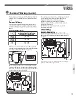
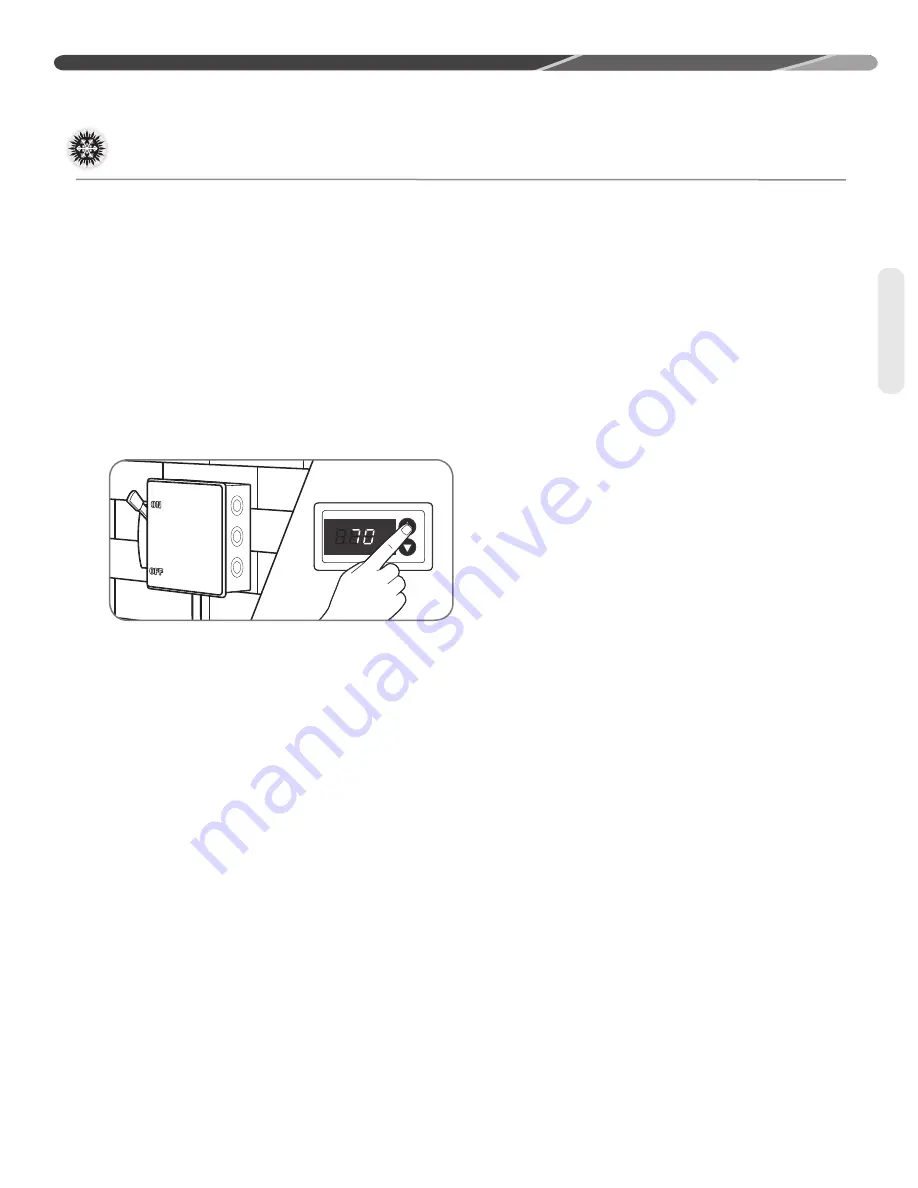
With thermostat in the “Off” position, turn on the
power to the furnace or air handler and the heat
pump� Start the heat pump and the furnace or air
handler with the thermostat� Verify that the outdoor
unit is operating in second stage and the indoor
air mover is delivering the second-stage airflow for
the system size�
Gross Charging by Pressures
1� Following airflow verification and charge weigh-
in, run the unit for a minimum of 15 minutes
prior to noting pressures and temperature�
IMPORTANT:
Indoor conditions
as measured at the indoor coil must be within
2°F [1.1°C] of the following during gross charge
(pressure) evaluation:
Cooling Mode: 80°F [26.7°C] Dry Bulb
Heating Mode: 70°F [21.1°C] Dry Bulb
NOTICE:
If the Indoor temperature is above
or below this range, run the system to bring the
temperature down or run the electric heat/furnace
to bring the temperature within this range� System
pressure values provided in the Charging Chart for
outdoor dry bulbs corresponding to conditions outside
of these ranges are provided as reference ONLY�
2� Note the Outdoor Dry Bulb Temperature,
ODDB° = _____°F [_____°C]� Unit charging is
recommended under the following outdoor
conditions ONLY:
Cooling Mode ONLY: 55°F [12.8°C] outdoor dry
bulb and above
Heating Mode ONLY: Between 40°F [4.4°C] and
60°F [15.6°C] outdoor dry bulb
3� Locate and note the design pressures� The
correct liquid and vapor pressures are found at
the intersection of the installed system and the
outdoor ambient temperature on the Charging
Chart located inside the access panel cover�
Liquid Pressure: = ______psig; Vapor Pressure =
______psig
NOTICE:
The refrigerant pressures provided
are for gross charge check ONLY� These pressure
values are typical, but may vary due to application�
Evaporator load (indoor coil in cooling mode/outdoor
coil in heating mode) will cause pressures to deviate�
Note that all systems have unique pressure curves�
The variation in the slope and value is determined
by the component selection for that indoor/outdoor
matched system� The variation from system to
system seen in the table is normal� The values listed
are for the applicable indoor coil match ONLY!
4� If the measured liquid pressure is below the
listed requirement for the given outdoor and
indoor conditions, add charge� If the measured
liquid pressure is above the listed requirement
for the given outdoor and indoor conditions,
remove charge�
Final Charge by Subcooling
1� After gross charging, note the designed
subcooling value� The correct subcooling value
is found at the intersection of the installed
system and the outdoor ambient temperature
on the Charging Chart located inside the access
panel cover�
SC° from Charging Chart = _____°F [_____°C].
IMPORTANT:
Indoor conditions as
measured at the indoor coil are required to be
between 70°F [21.1°C] and 80°F [26.7°C] dry
bulb for fine-tuned unit charge adjustment� Unit
charging is recommended under the following
outdoor conditions ONLY:
Cooling Mode ONLY: 55°F [12.8°C] outdoor dry
bulb and above
Heating Mode ONLY: Between 40°F [4.4°C] and
60°F [15.6°C] outdoor dry bulb
START-UP
Checking Refrigerant Charge (cont�)
Refrigerant
Summary of Contents for ANL-AZ 13 SEER Series
Page 12: ...12 INSTALLATION Interconnecting Tubing cont Tubing...
Page 13: ...13 INSTALLATION Interconnecting Tubing cont Tubing...
Page 14: ...14 INSTALLATION Interconnecting Tubing cont Tubing...
Page 35: ...35 For Single Phase Models WIRING DIAGRAMS Wiring Diagrams...
Page 36: ...36 WIRING DIAGRAMS For Three Phase Models Wiring Diagrams...
Page 37: ...37 Wiring Diagrams APM 018 WITH ECM FAN MOTOR WIRING DIAGRAMS...
Page 38: ...38 NOTES...
Page 39: ...39 NOTES...
Page 40: ...40 NOTES...

