25
While scroll compressors usually do not require
crankcase heaters, there are instances when a
heater should be added� Refrigerant migration
during the off cycle can result in a noisy start up�
Add a crankcase heater to minimize refrigerant
migration and to help eliminate any start up noise
or bearing “wash out�”
NOTE:
A crankcase heater should be installed if:
• The system charge exceeds the values listed in
the adjacent tables,
• The system is subject to low voltage variations,
or
• When a low ambient control is used for system
operation below 55°F�
All heaters are located on the lower half of the
compressor shell� Its purpose is to drive refrigerant
from the compressor shell during long off cycles,
thus preventing damage to the compressor during
start-up�
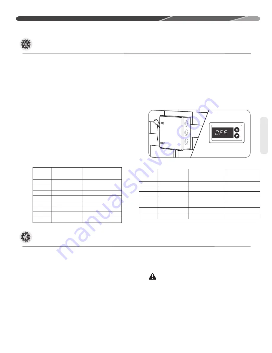
At initial start-up or after extended shutdown
periods, make sure the heater is energized for at
least 12 hours before the compressor is started�
(Disconnect switch is on and wall thermostat is off�)
Compressor Crankcase Heat (CCH)
High- and Low-Pressure Controls (HPC and LPC)
These controls keep the compressor from
operating in pressure ranges which can cause
damage to the compressor� Both controls are in
the low-voltage control circuit�
The high-pressure control (HPC) is an automatic-
reset which opens near 610 PSIG and closes near
420 PSIG�
The low-pressure control (LPC) is an automatic-
reset which opens near 15 PSIG and closes near
40 PSIG�
NOTICE:
HPC and LPC are monitored
by the
Comfort Control
2
System
™� See “
Comfort
Control
2
System
TM
” on page 26�
CAUTION:
The compressor has
an internal overload protector� Under some
conditions, it can take up to 2 hours for this
overload to reset� Make sure overload has had
time to reset before condemning the compressor�
COMPONENTS AND CONTROLS
(-)ANL
Charge Limit
Charge Limit
Model
Compressor
Without Crankcase
Without Crankcase
Size
Model Number
Heat (3 Phase)
Heat (1 Phase)
18
ZP16K5E
8 lbs.
9.6 lbs.
24
ZP21K5E
8 lbs.
9.6 lbs.
31
ZP25K5E
8 lbs.
9.6 lbs.
37
ZP34K5E
10 lbs.
12 lbs.
43
ZP38K5F
10 lbs.
12 lbs.
49
ZP42K5E
10 lbs.
12 lbs.
60
ZP54K5E
10 lbs.
12 lbs.
(-)APM
Charge Limit
Model
Compressor
Without Crankcase
Size
Model Number
Heat (1 Phase)
18
ZP16K5E
9.6 lbs.
24
ZP20K5E
9.6 lbs.
30
ZP24K5E
9.6 lbs.
36
ZP31K5E
9.6 lbs.
42
ZP34K5E
12 lbs.
48
ZP42K5E
12 lbs.
56
ZP44K5E
12 lbs.
60
ZP51K5E
12 lbs.
Components
Summary of Contents for ANL-AZ 13 SEER Series
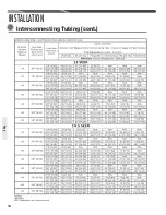
Page 12: ...12 INSTALLATION Interconnecting Tubing cont Tubing...
Page 13: ...13 INSTALLATION Interconnecting Tubing cont Tubing...
Page 14: ...14 INSTALLATION Interconnecting Tubing cont Tubing...
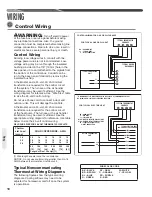
Page 35: ...35 For Single Phase Models WIRING DIAGRAMS Wiring Diagrams...
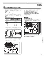
Page 36: ...36 WIRING DIAGRAMS For Three Phase Models Wiring Diagrams...
Page 37: ...37 Wiring Diagrams APM 018 WITH ECM FAN MOTOR WIRING DIAGRAMS...
Page 38: ...38 NOTES...
Page 39: ...39 NOTES...
Page 40: ...40 NOTES...


