26
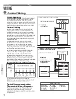
WARNING:
Turn off electric power
at the fuse box or service panel before making
any electrical connections� Also, the ground
connection must be completed before making line
voltage connections� Failure to do so can result in
electrical shock, severe personal injury, or death�
CAUTION:
SINGLE POLE COMPRESSOR
CONTACTOR (CC):
Single pole contactors are used on all single-
phase units up through 5 tons� Caution must be
exercised when servicing as only one leg of the
power supply is broken with the contactor� Two
pole contactors are used on some three-phase
units�
Time Delay Control
(Part No. RXMD-B01)
The time delay control is in the low voltage control
circuit� When the compressor shuts off due to a
power failure or thermostat operation, this control
keeps it off at least 5 minutes which allows the
system pressure to equalize, thus not damaging
the compressor or blowing fuses on start-up�
Low Ambient Control (LAC)
(Part No. RXAD-A08)
This component senses compressor head
pressure and shuts the heat pump fan off when
the head pressure drops to approximately 250
PSIG� This allows the unit to build a sufficient head
pressure at lower outdoor ambient (down to 0°F
[-18°C]) in order to maintain system balance and
obtain improved capacity� Low ambient control
should be used on all equipment operated below
70°F [21°C} ambient�
ACCESSORIES
Hard Start Components
Start components are not usually required with
the scroll compressors used in (-)ANL/(-)APM
condensing units, but are available for special
cases and where start components are desirable
to reduce light dimming�
Accessories
Summary of Contents for ANL-AZ 13 SEER Series
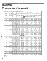
Page 12: ...12 INSTALLATION Interconnecting Tubing cont Tubing...
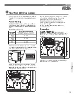
Page 13: ...13 INSTALLATION Interconnecting Tubing cont Tubing...
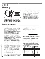
Page 14: ...14 INSTALLATION Interconnecting Tubing cont Tubing...
Page 35: ...35 For Single Phase Models WIRING DIAGRAMS Wiring Diagrams...
Page 36: ...36 WIRING DIAGRAMS For Three Phase Models Wiring Diagrams...
Page 37: ...37 Wiring Diagrams APM 018 WITH ECM FAN MOTOR WIRING DIAGRAMS...
Page 38: ...38 NOTES...
Page 39: ...39 NOTES...
Page 40: ...40 NOTES...


