10
11
1. Turn off power
WARNING:
Turn off
power to HVAC system
at circuit breaker
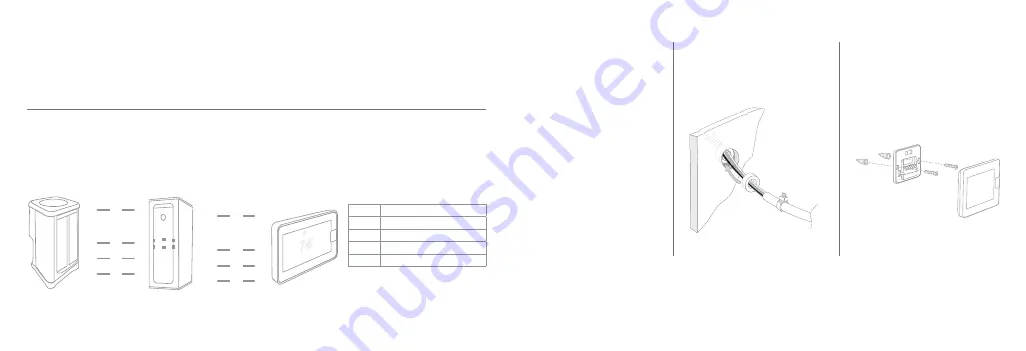
2. Place ferrite toroid
(if provided)
around
thermostat wires
and nest in drywall
3. Secure the wall plate
Use the dry wall anchors and
screws provided.
Wiring Diagram
Use 18 AWG or larger for normal wiring applications.
NOTE:
Four wires are required.
Wire units in a “daisy chain” and not in a “star” configuration.
The order of the devices in the network is not specified except the EcoNet Smart Thermostat should be at one
end of the network.
Terminal
Function
R
Power - 24VAC
C
Common / Ground - 24VAC
E1
EcoNet Communications Bus Wire 1
E2
EcoNet Communications Bus Wire 2
QUICK S
TART
GUIDE
E1
E2
C
R
R
E1
E2
S1
S2
C
R
E1
E2
C
OUTDOOR UNIT
INDOOR UNIT
OPTIONAL REMOTE
TEMPERATURE SENSOR
ECONET
SMART THERMOSTAT
R C S1 S2 E1 E2
QUICK S
TART
GUIDE
E1
E2
C
R
R
E1
E2
S1
S2
C
R
E1
E2
C
OUTDOOR UNIT
INDOOR UNIT
OPTIONAL REMOTE
TEMPERATURE SENSOR
ECONET
SMART THERMOSTAT
R C S1 S2 E1 E2
QUICK S
TART
GUIDE
E1
E2
C
R
R
E1
E2
S1
S2
C
R
E1
E2
C
OUTDOOR UNIT
INDOOR UNIT
OPTIONAL REMOTE
TEMPERATURE SENSOR
ECONET
SMART THERMOSTAT
R C S1 S2 E1 E2
Interior view of wall
Tip:
Ensure the back plate is
straight by centering the bubble
on the built-in level.


