background image

10

Installing the Water Heater:

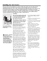
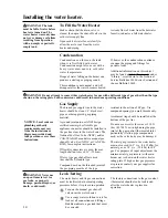
Blower Assembly Installation

Connect blower assembly with Molex connector.

Attach Blower Assembly to top pan using the five
screws (see diagram to the left).

Install rubber coupling (supplied in the box with
water heater) on blower housing and secure it.

Horizontal Vent Terminal Location

The location of the vent terminal depends on the
following minimum clearances and considerations (see
illustration):

Twelve (12) inches (30.5cm) above grade level and
above normal snow levels.

Four (4) feet (1.2m)

2

below, or four (4) feet (1.2m)

horizontally from any door, operable window, soffit,
under eave vent or gravity air inlet to the building or
other appliances, or from gas or electric meters. Do
not locate vent above walkways, doors,  windows, air
inlets, gas or electric meters or other equipment.

Three (3) feet (0.9m) above any forced air inlet lo-
cated within 10 feet (3,05m)³ of any fresh or make-
up air inlet such as for a dryer or furnace area is
considered to be a forced air inlet.
Eighteen (18) inches (45cm) from an inside corner
formed by two exterior walls, overhang, or
obstruction.

Additional Considerations

If soffit vent is too
close, block off and
install new vent at
another location

Inside
corner

Caulk

Caulk

Caulk

6' (1,83m)
caulk
zone or
to edge of
window etc., starting
 

within 6' (1,83m)

Rising moisture will
collect under eaves

4'

(1,20m)

6'

(1,83m)

6' (1,83m)
caulk
zone

Recommended
2 ft. sq.  (60 cm sq) 
sheet metal plate

RTV silicone caulk

WARNING

: Moisture in the flue gas will condense as it

leaves the vent terminal. In cold weather this condensate can
freeze on the exterior wall, under the eaves and on surrounding
objects. Some discoloration to the exterior of the building is to
be expected. However, improper location or installation can
result in severe damage to the structure or exterior finish of the
building.

Do Not install vent terminal under any patio or deck.

To help prevent moisture from freezing on walls and
under eaves, do not locate vent terminal on the side of
a building with prevailing winter winds.

Do Not terminate vent pipe directly on brick or
masonry surfaces. It is recommended to use a rust-
resistant sheet metal backing plate 2 x 2 feet 
(60cm x 60cm) behind vent. (See illustration.)

Do Not locate vent terminal too close to shrubbery, as
flue gasses may damage them.

Caulk all cracks, seams and joints within six (6) feet
(1,80m) of vent terminal.

All painted surfaces should be primed to lessen the
chance of physical damage. Painted surfaces will
require maintenance.

Insulate vent pipe exposed to cold conditions (attics,
crawl spaces, etc.) with inflammable material to help
prevent moisture from accumulating in vent pipe.

Do Not extend exposed vent pipe outside of building.

NOTICE: Canadian vent termination/location must
follow CSA B149 requirements and may vary from above.

2

For installations in Canada one (1) foot (0,30 m) is allowed.

3

For installations in Canada 6 feet (1.8m)

Electric
Meter

Inside
Corner

Window or Vent

Soffit Vents

12" (30.5cm) (Above grade/snow level)

4'

(1,20m)

18” 

(45 cm)

18” (45 cm)

Fresh
Air
Intake 

3' above if within 10'

4'

(1,20m)

4'

(1,20m)

4' (1,20m)

4'

(1,20m)

Summary of Contents for PowerVent 2

Page 1: ...mendations for the proper installation and adjustment of the water heater and two for the owner operator to explain the features operation safety precautions maintenance and troubleshooting of the wat...

Page 2: ...ite the model and serial numbers here You can find them on a label on the appliance Staple sales slip or cancelled check here Proof of the original purchase date is needed to obtain service under the...

Page 3: ...olvents paint thinners etc and the vapors they produce are extremely dangerous DO NOT handle use or store gasoline or other flammable or combustible materials anywhere near or in the vicinity of a wat...

Page 4: ...t the left details the approximate water temperature for each mark on the Gas Control Thermostat Temperature Dial DANGER Hotter water increases the potential for Hot Water SCALDS D A N G E R HOT Water...

Page 5: ...LP gas must be used with great caution It is heavier than air and will collect first in lower areas making it hard to detect at nose level Before attempting to light the water heater make sure to look...

Page 6: ...N READ ALL INSTRUCTIONS BEFORE USING WARNING For your safety the information in this manual must be followed to minimize the risk of fire or explosion electric shock or to prevent property damage pers...

Page 7: ...moving vehicles area flooding etc For these reasons installation of a gas fired water heater in a garage is not desirable Make certain the floor underneath the water heater is strong enough to suffic...

Page 8: ...not less than one square inch 6 5sq cm per 2000 Btuh of the total input rating of all the appliances in the enclosure If ducts are used the minimum dimensions of rectangular air ducts shall not be les...

Page 9: ...lp prevent the transmission of noise and vibration Do not support pin or otherwise secure the venting system in a way that restricts the normal thermal expansion and contraction of the chosen venting...

Page 10: ...WARNING Moisture in the flue gas will condense as it leaves the vent terminal In cold weather this condensate can freeze on the exterior wall under the eaves and on surrounding objects Some discolorat...

Page 11: ...nt that has become curdled lumpy or thickened DO NOT thin solvent cement Observe shelf precautions printed on the containers For applications below 32 F 0 C use only low temperature type solvent cemen...

Page 12: ...7 from any forced air inlet to the building Any fresh or make up air inlet such as a dryer or furnace area is considered to be a forced air inlet Short Piece of Vent Pipe Min 12 30 5cm 5 Above Roof Mi...

Page 13: ...ed to as thermal expansion In an open water system expanding water which exceeds the capacity of the water heater flows back into the city main where the pressure is easily dissipated A closed water s...

Page 14: ...rmostat inlet particularly if teflon pipe compound is used as the valve body may be damaged The inlet gas pressure to the water heater must not exceed 10 5 w c 2 625 kPa for natural gas or 14 w c 3 5...

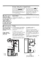
Page 15: ...ons up to 7 700 feet 2347m Installations above 7 700 feet 2347m are not permitted Pressure Testing the Gas Supply System The water heater and its manual gas shut off valve must be disconnected from th...

Page 16: ...ergy saving or other unapproved devices other than those authorized by the manufacturer into onto or in conjunction with the water heater The use of unauthorized energy saving devices may shorten the...

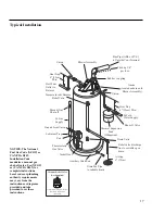
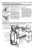
Page 17: ...ary C atch Pan Thermostatic Gas Valv e Jacket Door Ground Join t Union Drain Valv e Relief valve discharge line to suitable open drain Temperature Pr essure Relief Valv e Pitch up 1 4 per foot NOTICE...

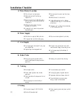
Page 18: ...rom water heater and piping Water connections tight and free of leaks Gas line equipped with shut off valve union and sediment trap Approved pipe joint compound used Soap and water solution used to ch...

Page 19: ...o an existing heating unit or components of a heating system that have previously been used with a non drinking water system Toxic chemicals such as those used for boiler treatment may be present and...

Page 20: ...and all other labels on the water heater as well as the warnings printed in this manual Failure to do so can result in unsafe operation of the water heater resulting in property damage personal injur...

Page 21: ...s newspaper rags or mops to accumulate near water heater Do Not store or use gasoline or other flammable vapors and liquids such as adhesives or paint thinner in vicinity of this or any other applianc...

Page 22: ...s who are incapacitated The gas control thermostat is constructed with a built in safety shut off device designed to shut off the gas supply to the burner if the pilot flame is extinguished for any re...

Page 23: ...thermostat sensors from accurately reading the water temperature the water at the fixture can be hotter than the gas control thermostat dial setting It is suggested that a few quarts of water be drai...

Page 24: ...er remove the burner from the water heater A vacuum cleaner can be used on the burner and floor shield inside the water heater The burner can also be cleaned by scrubbing with mild detergent Proper bu...

Page 25: ...r orifice clogged The pilot burner should be cleaned or replaced by a qualified service technician Pilot burner tube pinched or The pilot burner should be cleaned repaired or clogged replaced by a qua...

Page 26: ...oo high the valve will not operate Refer to Installing the water heater Clean any scale buildup from burner and pilot assembly The spark ignitor assembly could be damaged or broken If so replace assem...

Page 27: ...ng gas control thermostat burners vent connectors or other safety devices Refer repairs to qualified service personnel LP Burner Assembly Natural Gas Burner Assembly Gas Control Thermostat Inner Door...

Page 28: ...nter Park Drive Montgomery Alabama 36109 1413 Phone 1 800 432 8373 In Canada Rheem Canada Ltd Lt e 128 Barton Street West P O Box 2846 Station A Hamilton Ontario Canada L8N 3P3 Phone Customer Service...

Reviews: