background image

15

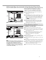
Additional Considerations


Do Not install vent terminal under any patio or deck.

  To help prevent moisture from freezing on walls and under  

eaves, do not locate vent terminal on the side of a build ing 

with prevailing winter winds.

  When terminating the vent pipe through brick or masonry 

surfaces, a rust-resistant sheet metal backing plate  

behind the vent termination is recommended. 

(See illustration.)

  Do Not locate vent terminal too close to shrubbery, as flue 

gasses may damage them.

  Caulk all cracks, seams and joints within six (6) feet of vent 

terminal.

  All painted surfaces should be primed to lessen the chance of 

physical damage. Painted surfaces will require maintenance.

  Insulate vent pipe exposed to cold conditions (attics, crawl 

spaces, etc.) with inflammable material to help prevent 

moisture from accumulating in vent pipe.


Do Not extend exposed vent pipe outside of building.

If soffit vent is too 

close, block off and 

install new vent at 

another location 

Inside 

corner 

Caulk 

Caulk 

Caulk 

6' (1.83 m) 

caulk 

zone or to edge of 

window etc., starting 


within 6' 

Rising moisture will 

collect under eaves 

    4'


6' caulk zone

2 ft. sq. sheet metal plate on

brick or masonary surface is recomended.

6' 

WARNING

Moisture in the flue gas will condense as it 

leaves the vent terminal. In cold weather this condensate can 

freeze on the exterior wall, under the eaves and on 

surrounding objects. Some discoloration to the exterior of 

the building is to be expected. However, improper location 

or installation can result in severe damage to the structure 

or exterior finish of the building

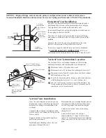
Horizontal Vent Terminal Location

The location of the vent terminal depends on the following 

minimum clearances and considerations (see illustration):

  Vent Terminal must be at least twelve (12) inches above 

grade level and above normal  

snow levels.

  Vent Terminal must be at least four (4) feet below, or four 

(4) feet horizontally from any door, operable window, soffit, 

under eave vent or gravity air inlet to the building or other 

appliances, or from gas or electric meters. Do not locate 

vent above walkways, doors,  windows, air inlets, gas or 

electric meters or other equipment.

  Vent Terminal must be at least three (3) feet above any 

forced air inlet located within ten (10) feet. Any fresh or 

make-up air inlet such as for a dryer or furnace area is 

considered to be a forced air inlet.

  Vent Terminal must be at least eighteen (18) inches from an 

inside corner formed by two exterior walls.

4'

4'

Soffit vents

18"

4'

4'

4'

18"

Electric

meter

Inside

corner

3' above

if within 10'

Fresh

air

intake

12" (Above grade/snow level)

window or vent

NOTICE: All pipe, fittings, solvent cement, primers and procedures must conform to American 

National Standards Institute and American Society for Testing and Materials (ANSI/ASTM) standards.

2 ft. sq. sheet metal plate on brick or 

masonry surface is recommended.

Summary of Contents for PowerVent AP14236

Page 1: ...he basic directions and recommendations for the proper installation and adjustment of the water heater and two for the owner operator to explain the features operation safety precautions maintenance a...

Page 2: ...time and money over the life of your water heater You ll find many answers to common problems in the Troubleshooting Guide If you review the chart of Troubleshooting Tips first you may not need to ca...

Page 3: ...s paint thinners etc and the vapors they produce are extremely dangerous DO NOT handle use or store gasoline or other flammable or combustible materials anywhere near or in the vicinity of a water hea...

Page 4: ...rature Dial D A N G E R HOT Water temperature over 125 F can cause severe burns instantly or death from scalds Children disabled and elderly are at highest risk of being scalded See instruction manual...

Page 5: ...LP gas must be used with great caution It is heavier than air and will collect first in lower areas making it hard to detect at nose level Before attempting to light the water heater make sure to look...

Page 6: ...installation For residential water heaters of a capacity greater than 52 gallons consult the local building jurisdiction for acceptable bracing procedures Have the installer show you the location of t...

Page 7: ...ate a shut down condition of the water heater which will not allow the water heater to ignite until examined by a Qualified Service Technician The water heater must be located so it is not subject to...

Page 8: ...than one square inch per 4000 Btuh of the total input rating of all the appliances in the enclosure If horizontal ducts are used to communicate with the outdoors each opening must have a minimum net...

Page 9: ...ondition and eliminating the repeated operation of the relief valve Other methods of controlling thermal expansion are also available Contact your installing contractor water supplier or plumbing insp...

Page 10: ...ncealed and should be protected from freezing No valve of any type restriction or reducer coupling should be installed in the discharge line To Fill the Water Heater Make certain that the drain valve...

Page 11: ...s supply piping at pressures equal to or less than 3 8 psi 10 5 w c for natural gas or 1 2 psi 14 w c for LP gas Gas Supply The branch gas supply line to the water heater should be clean 1 2 black ste...

Page 12: ...nual have been met Carefully inspect the entire venting system for any signs of cracks or fractures particularly at the joints between elbows or other fittings and the straight length of vent pipe Che...

Page 13: ...s For the 2 vent one 90 elbow is approximately equal to 6 feet of vent pipe One 45 elbow is approximately equal to 3 feet of vent pipe Minimum vent length for 2 vent pipe is one 1 foot of vertical pip...

Page 14: ...t Pipe Length in Feet ft 0 Maximum Altitude See chart on upper left One 1 None 95 One 1 One 1 92 5 Two 2 None 90 Two 2 One 1 87 5 Three 3 None 85 Three 3 One 1 82 5 Four 4 None 80 Four 4 One 1 77 5 Fi...

Page 15: ...xterior wall under the eaves and on surrounding objects Some discoloration to the exterior of the building is to be expected However improper location or installation can result in severe damage to th...

Page 16: ...without additional support for vent Four 4 feet from any gable dormer or other roof structure with building interior access i e vent window etc Ten 10 feet from any forced air inlet to the building A...

Page 17: ...the joint with a rag Allow 15 minutes before handling Cure time will vary according to fit temperature and humidity NOTICE Stir the solvent cement frequently while using Use a natural bristle brush or...

Page 18: ...nce with latest edition of the National Electric Code ANSI NFPA No 70 Refer to the figures below for water heater internal wiring NOTE It is not recommended that this unit be installed on a GFCI circu...

Page 19: ...ication of an external insulation blanket to this water heater pay careful attention to the following so as not to restrict the proper function and operation of the water heater Do not cover the opera...

Page 20: ...cess Door unless absolutely necessary This should only be done by a qualified service technician A new burner access door gasket must be installed on any burner access door that has been removed DON T...

Page 21: ...and free of leaks Gas line equipped with shut off valve union and sediment trap Approved pipe joint compound used Soap and water solution used to check all connections and fittings for possible gas l...

Page 22: ...ating Installation Spring loaded check valve in heating unit hot water supply line and cold water return line not supplied with water heater NOTE This check valve is incorporated in some heating units...

Page 23: ...s phone Follow the gas suppliers Do not try to light any appliance Do not touch any electric switch do not use any phone in your building WHAT TO DO IF YOU SMELL GAS 9 10 Stop Read the safety informa...

Page 24: ...temperature of the water in the water heater can be regulated by pressing the buttons on the front of the gas control thermostat Safety and energy conservation are factors to be considered when selec...

Page 25: ...refore always remember to test the water temperature with your hand before use and remember that hotter water increases the risk of scald injury Also always supervise young children or others who are...

Page 26: ...as valve which will extinguish the main burner flames The blower motor will stay energized for an additional 30 seconds after the control verifies that the burner flame is extinguished in order to cle...

Page 27: ...ef valve on the water heater discharges periodically this may be due to thermal expansion in a closed water system Contact the water supplier or your plumbing contractor on how to correct this DO NOT...

Page 28: ...ealed area If the burner access door is removed the burner access door gasket must be replaced For cleaning remove the burner from the water heater A vacuum cleaner can be used on the burner and floor...

Page 29: ...Gas Caution in the Operating Instructions Anode Rod This water heater is equipped with an anode rod designed to prolong the life of the glass lined tank The anode rod is slowly consumed thereby elimin...

Page 30: ...inlet openings on water heater jacket Not enough combustion or Proper operation of the water heater requires air for ventilation air supplied to combustion and ventilation See the Combustion and the...

Page 31: ...ion Shutoff System Contact a qualified service technician tripped Water is too hot The gas control thermostat See the Water Temperature Setting of The Water is set too high Heater section of this manu...

Page 32: ...d A B C Error in the hot surface ignitor cir cuit 1 Check that all wiring is correct and secure 2 Replace hot surface ignitor A B C System in lockout 1 Gas supply is off or too low to operate 2 Hot su...

Page 33: ...hermostat burners vent connectors or other safety devices Refer repairs to qualified service personnel Use only original equipment replacement parts Blower Assembly Flue baffle and hanger Anode rod He...

Page 34: ...34 Notes...

Page 35: ...35 Notes...

Page 36: ...an attic the hard wired carbon monoxide detec tor with alarm and battery back up may be installed on the next adjacent floor level b In the event that the requirements of this subdivision can not be...

Reviews: