C. CLEARANCES
The following minimum clearances must be observed for prop-
er unit performance and serviceability.
1. Provide 80" minimum clearance at the front of the unit.
Provide 18" minimum clearance at all other sides of the unit.
2. Provide 60" minimum clearance between top of unit and
maximum 3 foot overhang.
3. Unit is design certified for application on combustible floor-
ing with 0" minimum clearance.
4. See Figure 9 for illustration of minimum installation-service
clearances.
D. ROOFTOP INSTALLATION
1. Before locating the unit on the roof, make sure that the
strength of the roof and beams is adequate at that point to
support the weight involved. This is very important and
user’s responsibility.
2. For rigging and roofcurb details, see Figures 11 and 12. Use
field-furnished spreaders.
3. For roofcurb assembly, see Roofcurb Installation Instruc-
tions.
4. If the roofcurb is not used, provisions for disposing of con-
densate water runoff must be provided.
5. The unit should be placed on a solid and level roofcurb or
platform of adequate strength. See Figure 13.
6. The location of the unit on the roof should be such as to pro-
vide proper access for inspection and servicing.
IMPORTANT: If unit will not be put into service immediately,
cover supply and return openings to prevent excessive con-
densation.
32%
27%
16%
24%
CORNER WEIGHTS MEASURED AT BASE OF UNIT.
FIGURE 11
ST-A1125-25
PACKAGED HEAT PUMP
RIGGING FOR LIFTING
PACKAGED HEAT PUMP
ROOFCURB INSTALLATION
UNIT BASE FRAME
ROOFTOP UNIT
ROOFCURB
ROOF FLASHING
ROOFING
CANT STRIP
ROOF DECK
INSULATION
INSULATION
DUCT
NAILER STRIP
GASKET
ST-A0888-02
FIGURE 12
UNIT
ST-A1125-14
ROOFCURB
INSTALL GASKET
DUCT FLANGE NOT
TO EXCEED
1” [25 mm]
RETURN DUCT
50-3/4” X 22” [1289 x 559 mm] MAX
SUPPLY DUCT
42” X 23-3/4” [1089 X 603 mm] MAX
CAULK ALL JOINTS
WATERTIGHT
NAILING STRIP
13
Summary of Contents for RJNL-B SERIES
Page 25: ...25...
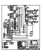
Page 26: ...26 NOTE 15 TON UNIT DOES NOT HAVE OFM 2 5...
Page 28: ...28 CM 0913 RJNL SERIES 15 TON...


