34
With an accurate scale (+/– 1 oz. [28.3 g]) or
volumetric charging device, adjust charge
difference between that shown on the unit data
plate and that calculated for the new system
installation. If the entire system has been
evacuated, add the total calculated charge.
IMPORTANT:
Charging by weight is
not always accurate since the application can
affect the optimum refrigerant charge. Charging by
weight is considered a starting point ONLY. Always
check the charge by using the Charging Chart
and adjust as necessary. CHARGING BY LIQUID
SUBCOOLING MUST BE USED FOR FINAL
CHARGE ADJUSTMENT.
With thermostat in the “Off” position, turn on the
power to the furnace or air handler and the heat
pump. Start the heat pump and the furnace or air
handler with the thermostat. Verify that the outdoor
unit is operating in second stage and the indoor
air mover is delivering the correct airflow for the
system size.
Gross Charging by Pressures
1. Following airflow verification and charge weigh-
in, run the unit for a minimum of 15 minutes
prior to noting pressures and temperature.
IMPORTANT:
Indoor conditions
as measured at the indoor coil must be within
2°F [1.1°C] of the following during gross charge
(pressure) evaluation:
Cooling Mode: 80°F [26.7°C] Dry Bulb
Heating Mode: 70°F [21.1°C] Dry Bulb
NOTICE:
If the Indoor temperature is above
or below this range, run the system to bring the
temperature down or run the electric heat/furnace
to bring the temperature within this range. System
pressure values provided in the Charging Chart for
outdoor dry bulbs corresponding to conditions outside
of these ranges are provided as reference ONLY.
2. Note the Outdoor Dry Bulb Temperature,
ODDB° = _____°F [_____°C]. Unit charging is
recommended under the following outdoor
conditions ONLY:
Cooling Mode ONLY: 55°F [12.8°C] outdoor dry
bulb and above
Heating Mode ONLY: Between 40°F [4.4°C] and
60°F [15.6°C] outdoor dry bulb
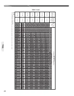
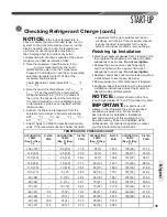
3. Locate and note the design pressures. The
correct liquid and vapor pressures are found at
the intersection of the installed system and the
outdoor ambient temperature on the Charging
Chart located inside the access panel cover.
Liquid Pressure: = ______psig; Vapor Pressure =
______psig
NOTICE:
The refrigerant pressures provided
are for gross charge check ONLY. These pressure
values are typical, but may vary due to application.
Evaporator load (indoor coil in cooling mode/outdoor
coil in heating mode) will cause pressures to deviate.
Note that all systems have unique pressure curves.
The variation in the slope and value is determined
by the component selection for that indoor/outdoor
matched system. The variation from system to
system seen in the table is normal. The values listed
are for the applicable indoor coil match ONLY!
4. If the measured liquid pressure is below the
listed requirement for the given outdoor and
indoor conditions, add charge. If the measured
liquid pressure is above the listed requirement
for the given outdoor and indoor conditions,
remove charge.
Final Charge by Subcooling
1. After gross charging, note the designed
subcooling value. The correct subcooling value
is found at the intersection of the installed
system and the outdoor ambient temperature
on the Charging Chart located inside the access
panel cover.
SC° from Charging Chart = _____°F [_____°C].
IMPORTANT:
Indoor conditions as
measured at the indoor coil are required to be
between 70°F [21.1°C] and 80°F [26.7°C] dry
bulb for fine-tuned unit charge adjustment. Unit
charging is recommended under the following
outdoor conditions ONLY:
Cooling Mode ONLY: 55°F [12.8°C] outdoor dry
bulb and above
Heating Mode ONLY: Between 40°F [4.4°C] and
60°F [15.6°C] outdoor dry bulb
START-UP
Checking Refrigerant Charge (cont.)
Refrigerant
Summary of Contents for RP13
Page 50: ...50 FOR SINGLE PHASE WITH PSC FAN MOTORS WIRING DIAGRAMS Wiring Diagrams...
Page 51: ...51 Wiring Diagrams WIRING DIAGRAMS 3 PHASE 208 230V MODELS...
Page 52: ...52 Wiring Diagrams WIRING DIAGRAMS FOR 3 PHASE 460 575V...
Page 54: ...54...
Page 55: ...55...
Page 56: ...56 CM 0815...

