4
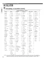
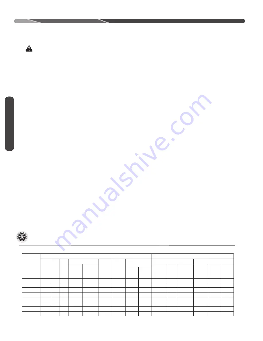
Model
Number
Voltage Phase
Freq
Rated Load
Amperes
(RLA)
Locked Roto r
Amperes
(LRA)
Fan
Motor
Full
Load
Amperes
(FLA )
Minimum
Circuit
Ampacity
Amperes
Minimum
Amperes
Maximum
Amperes
Face
Area
Sq. Ft .
[m
2
]
No.
Rows
CFM
[L/s]
Refrig .
Per
Circuit
(oz. )
[g]
Net
Lbs.
[kg]
Shipping
Lbs. [kg]
Fuse or HACR
Circuit Breaker
Outdoor Coil
We ight
Compressor
ELECTRICAL
PHYSICAL
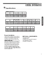
RP1336AC1NA 208-230 3 60 10.4 73.0 0.60 14
20/20
20/20 14.82 [1.38] 1 3333 [1573]
111 [3146] 171 [77.6] 184 [83.5]
RP1342AC1NA 208-230 3 60
13.5 88.0 1.00 18
25/25
30/30 14.82 [1.38] 1 2933 [1384]
201 [91.2] 208 [94.3]
RP1348AC1NA 208-230 3 60
13.7 83.1 1.20 19
25/25
30/30 19.76 [1.84] 1 4055 [1913] 143 [4054] 227 [103.0] 234 [106.1]
RP1360AC1NA 208-230 3 60
15.9 110.0 1.00 21
25/25
35/35 24.23 [2.25] 1 4780 [2255] 232 [6577] 262 [118.8] 269 [122.0]
RP1336AD1NA
460
3 60
5.8
38.0 0.50
8
15/15
15/15 14.82 [1.38] 1 3333 [1573] 111 [3146] 171 [77.6] 178 [80.7]
RP1348AD1NA
460
3 60
6.2
41.0 0.60
9
15/15
15/15 19.76 [1.84]
1 4055 [1913] 143 [4054]
227 [103.0] 234 [106.1]
RP1360AD1NA
460
3 60
7.1
52.0 0.50
10
15/15
15/15 24.23 [2.25]
1 4780 [2255] 232 [65717]
262 [118.8] 269 [122.0]
RP1342AD1NA
460
3 60
6.0
44.0 0.50
8
15/15
15/15 14.82 [1.38]
1 2933 [1384]
155 [4394]
155 [4394]
201 [91.2] 208 [94.3]
GENERAL INFORMATION
WARNING:
Improper installation, or installation not made in
accordance with these instructions, can result
in unsatisfactory operation and/or dangerous
conditions and can cause the related warranty
not to apply.
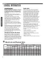
The RP series of heat pumps are designed to
operate with standard 24 VAC thermostats and air
handlers or gas furnaces.
This installation instruction manual contains
complete instructions for installation and setup
using conventional 24 VAC controls. Please refer
to the manufacturer’s specification sheets for
complete performance data, thermostat, and
accessory listings.
The information contained in this manual has
been prepared to assist in the proper installation,
operation, and maintenance of the air conditioning
system.
Read this manual and any instructions packaged
with separate equipment required to make up the
system prior to installation. Homeowner should
retain this manual for future reference.
To achieve optimum efficiency and capacity,
the matching indoor cooling coils listed in the
manufacturer’s specification sheet must be used
for this model heat pump.
Checking Product Received
Upon receiving unit, inspect it for any shipping
damage. Claims for damage, either apparent or
concealed, should be filed immediately with the
shipping company. Check model number, electrical
characteristics, and accessories to determine if they
are correct. Check system components (indoor coil,
outdoor unit, air handler/furnace, etc.) to make sure
they are properly matched.
Application
Before specifying any heat pump equipment,
a survey of the structure and a heat loss and
heat gain calculation must be made. A heat loss
calculation involves identifying all surfaces and
openings that lose heat to the surrounding air
and quantifying that heat loss. A cooling heat
gain calculation makes similar measurements
and determines the amount of heat needed
to be removed. A heat gain calculation also
calculates the extra heat load caused by sunlight
and by humidity removal. These factors must
be considered before selecting a heat pump
system to provide year-round comfort. The Air
Conditioning Contractors of America (ACCA)
J Manual method of load calculation is one
recognized procedure for determining the heating
and cooling load.
After the proper equipment combination has
been selected, satisfying both sensible and
latent requirements, the system must be properly
installed. Only then can the unit provide the
comfort it was designed to provide.
There are several factors that installers must
consider.
•
Outdoor unit location
•
Indoor unit blower speed and airflow
•
Proper equipment evacuation
•
Supply and return air duct design and sizing
•
Refrigerant charge
•
System air balancing
•
Diffuser and return air grille location and sizing
General Information
Electrical and Physical Data
RP13
Summary of Contents for RP13
Page 50: ...50 FOR SINGLE PHASE WITH PSC FAN MOTORS WIRING DIAGRAMS Wiring Diagrams...
Page 51: ...51 Wiring Diagrams WIRING DIAGRAMS 3 PHASE 208 230V MODELS...
Page 52: ...52 Wiring Diagrams WIRING DIAGRAMS FOR 3 PHASE 460 575V...
Page 54: ...54...
Page 55: ...55...
Page 56: ...56 CM 0815...

