45
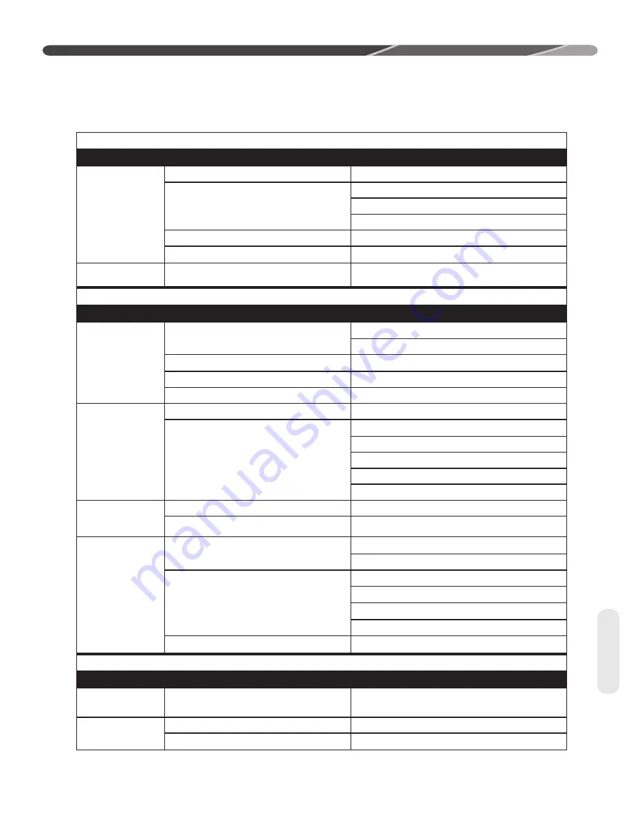
DIAGNOSTICS
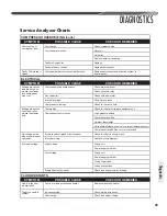
Service Analyzer Charts
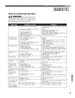
COMPRESSOR OVERHEATING (cont.)
SYMPTOM
POSSIBLE CAUSE
CHECK OR REMEDIES
Short cycling of
compressor (cont.)
Low charge
Check system charge.
Low evaporator air
fl
ow
Dirty coil
Dirty
fi
lter
Duct too small or restricted
Faulty run capacitor
Replace.
Faulty internal overload
Replace compressor.
Faulty Compressor
Valves
Fast equalization/Low pressure di
ff
erence
Replace compressor and examine system to
locate reason.
ELECTRICAL
SYMPTOM
POSSIBLE CAUSE
CHECK OR REMEDIES
Voltage present on
load side of com-
pressor contactor
and compressor
won't run
Compressor start components
Check start capacitor.
Check potential relay.
Run capacitor
Check with ohmmeter
Internal overload
Allow time to reset.
Compressor windings
Check for correct ohms.
Voltage present on
line side of com-
pressor contactor
only
Thermostat
Check for control voltage to contactor coil.
Compressor control circuit
High-pressure switch
Low-pressure switch
Ambient thermostat
Solid-state protection control or internal thermal sensors
Compressor timed o
ff
/on control or interlock
No voltage on line
side of compressor
contactor
Blown fuses or tripped circuit breaker
Check for short in wiring or unit.
Improper wiring
Recheck wiring diagram.
Improper voltage
High voltage
Wrong unit
Power supply problem
Low voltage
Wrong unit
Power supply problem
Wiring undersized
Loose connections
Single Phasing (3 phase)
Check incoming power and fusing.
FLOODED STARTS
SYMPTOM
POSSIBLE CAUSE
CHECK OR REMEDIES
Liquid in the com-
pressor shell
Faulty or missing crankcase heater
Replace crankcase heater.
Too much liquid in
system
Incorrect piping
Check piping guidelines.
Overcharge
Check and adjust charge.
Diagnostics
Summary of Contents for RP13
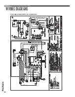
Page 50: ...50 FOR SINGLE PHASE WITH PSC FAN MOTORS WIRING DIAGRAMS Wiring Diagrams...
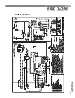
Page 51: ...51 Wiring Diagrams WIRING DIAGRAMS 3 PHASE 208 230V MODELS...
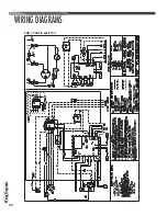
Page 52: ...52 Wiring Diagrams WIRING DIAGRAMS FOR 3 PHASE 460 575V...
Page 54: ...54...
Page 55: ...55...
Page 56: ...56 CM 0815...

