46
DIAGNOSTICS
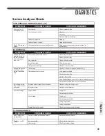
Service Analyzer Charts
SYMPTOM
POSSIBLE CAUSE
REMEDY
Moisture
Poor evacuation on installation or during service
In each case, the cure is the same. Recover refrigerant.
Add
fi
lter drier, evacuate, and recharge.
High head pressure
Noncondensibles air
Unusual head and
suction readings
Wrong refrigerant or mixed refrigerants
Foreign matter –
copper
fi
lings
Copper tubing cuttings
Copper oxide
Dirty copper piping or nitrogen not used when
brazing
Welding scale
Nitrogen not used during brazing
Soldering
fl
ux
Adding
fl
ux before seating copper partway
Excess soft solder
Wrong solder material
LOSS OF LUBRICATION
SYMPTOM
POSSIBLE CAUSE
REMEDY
Compressor failures
Line tubing too large
Reduce pipe size to improve oil return.
Low suction pressure
Low charge
Check system charge.
Refrigerant leaks
Repair and recharge.
Cold, noisy
compressor –
Slugging
Dilution of oil with refrigerant
Observe piping guidelines.
Noisy compressor
Migration
Check crankcase heater.
Cold, sweating
compressor
Flooding
Check system charge.
Low load
Reduced air
fl
ow
Dirty
fi
lter
Dirty coil
Wrong duct size
Restricted duct
Thermostat setting
Advise customer.
Short cycling of
compressor
Faulty high- or low-pressure control
Replace control.
Loose wiring
Check all control wires.
Thermostat
In supply air stream, out of calibration
Customer misuse
SLUGGING
SYMPTOM
POSSIBLE CAUSE
REMEDY
On start-up
Incorrect piping
Review pipe size guidelines.
TEV hunting when
running
Faulty TEV
Replace TEV.
CONTAMINATION
Diagnostics
Summary of Contents for RP13
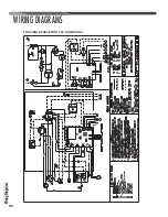
Page 50: ...50 FOR SINGLE PHASE WITH PSC FAN MOTORS WIRING DIAGRAMS Wiring Diagrams...
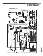
Page 51: ...51 Wiring Diagrams WIRING DIAGRAMS 3 PHASE 208 230V MODELS...
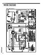
Page 52: ...52 Wiring Diagrams WIRING DIAGRAMS FOR 3 PHASE 460 575V...
Page 54: ...54...
Page 55: ...55...
Page 56: ...56 CM 0815...

