47
Diagnostics
DIAGNOSTICS
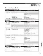
Service Analyzer Charts
FLOODING
SYMPTOM
POSSIBLE CAUSE
REMEDY
Poor system control
using a TEV
Loose sensing bulb
Secure the bulb and insulate.
Bulb in wrong location
Relocate bulb.
Wrong size TEV
Use correct replacement.
Improper superheat setting (less than 5°F [-15°C]) Replace TEV.
THERMOSTATIC EXPANSION VALVES
SYMPTOM
POSSIBLE CAUSE
REMEDY
High Superheat, Low
Suction Pressure
(superheat over
15°F [-9°C])
Moisture freezing and blocking valve
Recover charge, install
fi
lter-drier, evacuate system,
recharge.
Dirt or foreign material blocking valve
Recover charge, install
fi
lter-drier, evacuate system,
recharge.
Low refrigerant charge
Correct the charge.
Vapor bubbles in liquid line
Remove restriction in liquid line. Correct the refrigerant
charge.
Remove noncondensible gases.
Size liquid line correctly.
Misapplication of internally equalized valve
Use correct TEV.
Plugged external equalizer line
Remove external equalizer line restriction.
Undersized TEV
Replace with correct valve.
Loss of charge from power head sensing bulb
Replace power head or complete TEV.
Charge migration from sensing bulb to power
head (Warm power head with warm, wet cloth.
Does valve operate correctly now?)
Ensure TEV is warmer than sensing bulb.
Valve feeds too much
refrigerant, with low
superheat and higher
than normal suction
pressure
Moisture causing valve to stick open.
Recover refrigerant, replace
fi
lter-drier, evacuate system,
and recharge.
Dirt or foreign material causing valve to stick
open
Recover refrigerant, replace
fi
lter drier, evacuate system,
and recharge.
TEV seat leak (a gurgling or hissing sound is
heard AT THE TEV during the o
ff
cycle, if this is
the cause). NOT APPLICABLE TO BLEED PORT
VALVES.
Replace the TEV.
Oversized TEV
Install correct TEV.
Incorrect sensing bulb location
Install bulb with two mounting straps, in 2:00 or 4:00
position on suction line, with insulation.
Low superheat adjustment
Replace TEV.
Incorrectly installed, or restricted external
equalizer line
Remove restriction, or relocate external equalizer.
Summary of Contents for RP13
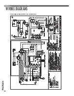
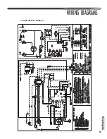
Page 50: ...50 FOR SINGLE PHASE WITH PSC FAN MOTORS WIRING DIAGRAMS Wiring Diagrams...
Page 51: ...51 Wiring Diagrams WIRING DIAGRAMS 3 PHASE 208 230V MODELS...
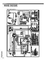
Page 52: ...52 Wiring Diagrams WIRING DIAGRAMS FOR 3 PHASE 460 575V...
Page 54: ...54...
Page 55: ...55...
Page 56: ...56 CM 0815...

