18
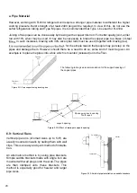
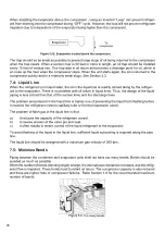
Figure 5.07: Too long horizontal length.
Figure 5.08: Excessive height different.
6.7: Minimize The Equivalent Length
The system does not
per
form correctly
whe
n
bo
th
the condenser and
evapora
tor units are too far
awa
y fromeach other
(e
ither vertically or
horizon-
tally
)
. The required refrigerant quantity increases
and the
prod
ucts’ guaranteed range is
ex
ceeded.
Also, the circulation of refrigerant and
lubri
cation
oil malfunctions, the ca
p
acity dro
p
s, and com
p
res
-
sor tr
oubl
e may occur.
The
pipin
g length should
b
e as short as
po
s
sibl
e
be
cause the ca
p
acity and the
reliabili
ty decreases
as
pipi
nglength increases.
S
elect the shortest
length
pos
s
ibl
e. Refer
S
ection T
able
#
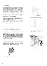
6.6: Oil Trap
Figure 5.06:
Figure 5.06:
vals along the
V
ertical suction
pipe. This
is
espe-
cially so
when
the outdoor unit is located on a
higher elevation than the indoor unit. These oil
traps
help
to get any accumulated oil to move
upwards,
as
shown
in
Figure
2.1. The design of
the
traps
will
forcibly
cause the gaseous
refriger-
ant to
pass
through the oil thus, carrying it
upwards back to the compresso
r.
As a guideline, an oil tra
p
is required at every 1
0
to 1
5
ft
(3
–
4
.6m
)
intervals
F
igure 2.
0
2 illustrates ho
w
oil tra
p
s are installed.
How
ever, the high
p
ressure dro
p
across such
tra
p
s may cause high ca
p
acity reduction.
Summary of Contents for SON Series
Page 1: ...Installation Operationand Service Manual _SONSeries ...
Page 2: ...02 ...
Page 4: ...1 0 SAFETY INSTRUCTIONS 1 1 WARNINGS 04 ...
Page 9: ...09 4 0 ELECTRICAL PHYSICAL DATA _SON ROTARY ...
Page 10: ...10 6 PHYSICAL AND ELECTRICAL DATA 4 1 TECHNICAL SPECIFICATION _SIN _SON ROTARY UNITS ...
Page 13: ...13 5 0 UNIT DIMENSION _SON SCROLL UNITS ...
Page 16: ...16 6 5 Things you may do ...
Page 17: ...17 ...
Page 26: ...26 7 4 Liquid Line 7 5 Minimize Bends ...
Page 28: ...28 9 0 REFRIGERANT CHARGE 0 4 0 6 0 3 9 1 Charging by Weight 9 2 Contamination ...
Page 29: ...29 ...
Page 30: ...30 10 2 Grounding 10 3 Control Wiring 10 01 Power Wiring 10 0 ELECTRICAL WIRING ...
Page 32: ...32 12 0 ELECTRICAL WIRING DIAGRAM Rotary RSON Rotary ...
Page 33: ...33 12 2 ELECTRICAL WIRING DIAGRAM Scroll RSON Scroll Single Phase ...
Page 34: ...34 12 1 ELECTRICAL WIRING DIAGRAM Scroll RSON Scroll Three Phase ...
Page 35: ...35 13 0 TROUBLE SHOOTING 13 1 Flow Chart ...
Page 36: ...36 14 0 OPERATION 18 45o C 20 a b a b c ...
Page 37: ...37 ...
Page 38: ...38 ...
Page 39: ...39 20 ...
Page 40: ...40 ...
Page 41: ...41 14 1 Error Code ...
Page 42: ...Notes ...
Page 43: ...Notes ...


