21
6.10 CRANKCASE HEATER STANDARD
WITH “OS” MODEL
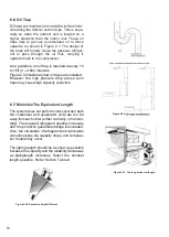
Figure 5.10: Example of crankcase heater
Crankcase heater is a sealed heater installed with
close contact to the outer circumference at the
bottom of the compressor. Examples of crank-
case heater and how crankcase heater is installed
onto a compressor is shown in Figure 2.8, Figure
2.9, and Figure 2.10.
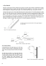
Figure 5.14: Vertical pipe installation on cable tray
Figure 5.15: Trunking box
Another method of running these pipes is by
using electrical cable trays. These pre-
fabricated trays are mounted onto the wall by
using saddle brackets. The copper pipes are
then clamped onto the trays. The main advan-
tage of using these trays is a very neat, organ-
ized, and clean installation.
Another similar method is by using trunking
boxes.The trunking can be mounted straight onto
the wall with wall plugs or on brackets. Copper
pipes are then inserted into the trunking. The
main advantage is that the pipes will be covered
and protected from damage.
The purpose of installing crankcase heater is to protect the compressor from the negative effects of the
liquid refrigerant in the compressor and in the lubricating oil. In simple words, crankcase heaters are
frequently used to retard migration. It removes the refrigerant by heating from the outside. Refrigerant
entering the compressor will be vaporized and driven back into the suction line. Crankcase heater
should be installed during long piping installations where the risk of liquid refrigerant migration is much
higher.
The crankcase heater size differs according to the capacity and the application of the compressor. A
heater of about 40W to 80W should be used.
When the compressor is inactive for a long period, the crankcase heater should be energized for at
least 6 to 12 hours before operation of the compressor is started. Please note that burning might occur
if oil gets on to the crankcase heater.
Deterioration due to water condensation and acoustic insulation materials (such as “pheuol products”)
can lead to defective insulation.
Summary of Contents for SON Series
Page 1: ...Installation Operationand Service Manual _SONSeries ...
Page 2: ...02 ...
Page 4: ...1 0 SAFETY INSTRUCTIONS 1 1 WARNINGS 04 ...
Page 9: ...09 4 0 ELECTRICAL PHYSICAL DATA _SON ROTARY ...
Page 10: ...10 6 PHYSICAL AND ELECTRICAL DATA 4 1 TECHNICAL SPECIFICATION _SIN _SON ROTARY UNITS ...
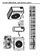
Page 13: ...13 5 0 UNIT DIMENSION _SON SCROLL UNITS ...
Page 16: ...16 6 5 Things you may do ...
Page 17: ...17 ...
Page 26: ...26 7 4 Liquid Line 7 5 Minimize Bends ...
Page 28: ...28 9 0 REFRIGERANT CHARGE 0 4 0 6 0 3 9 1 Charging by Weight 9 2 Contamination ...
Page 29: ...29 ...
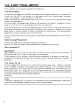
Page 30: ...30 10 2 Grounding 10 3 Control Wiring 10 01 Power Wiring 10 0 ELECTRICAL WIRING ...
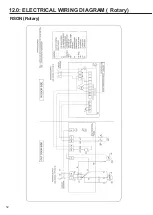
Page 32: ...32 12 0 ELECTRICAL WIRING DIAGRAM Rotary RSON Rotary ...
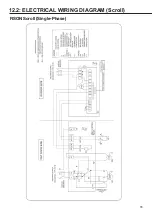
Page 33: ...33 12 2 ELECTRICAL WIRING DIAGRAM Scroll RSON Scroll Single Phase ...
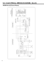
Page 34: ...34 12 1 ELECTRICAL WIRING DIAGRAM Scroll RSON Scroll Three Phase ...
Page 35: ...35 13 0 TROUBLE SHOOTING 13 1 Flow Chart ...
Page 36: ...36 14 0 OPERATION 18 45o C 20 a b a b c ...
Page 37: ...37 ...
Page 38: ...38 ...
Page 39: ...39 20 ...
Page 40: ...40 ...
Page 41: ...41 14 1 Error Code ...
Page 42: ...Notes ...
Page 43: ...Notes ...

