T
27
8.1 LEAK TESTING
Indoor coils have only a holding charge of dry nitrogen. Keep all tube ends sealed until connections
are to be made.
!
WARNING
DO NOT USE OXYGEN TO PURGE LINES OR PRESSURIZE SYSTEM FOR LEAK TEST. OXYGEN
REACTS VIOLENTLY WITH OIL, WHICH CAN CAUSE AN EXPLOSION RESULTING IN SEVERE
PERSONAL INJURY OR DEATH.
8.2 VACUUM TEST
8.0 LEAK TEST & VACUUM TEST
• Pressurize line set and coil through service fittings with dry nitrogen to 150 PSIG maximum. Close
nitrogen tank valve, let system sit for at least 15 minutes, and check to see if the pressure has
dropped. If the pressure has dropped, check for leaks at the line set braze joints with soap bubbles
and repair leak as necessary. Repeat pressure test. If line set and coil hold pressure, proceed with
line set and coil evacuation (see page 21)
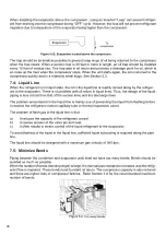
• The vapor line must be insulated for its entire length to prevent dripping (sweating) and prevent
performance losses. Closed-cell foam insulation such as Armaflex and Rubatex® are satisfactory
insulations for this purpose. Use 1/2" [12.7 mm] minimum insulation thickness. Additional insulation
may be required for long runs.
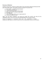
Evacuation is the most important part of the entire service procedure. The life and efficiency of the
equipment is dependent upon the thorough ness exercised by the serviceman when evacuating air
and moisture from the system.
Air or nitrogen in the system causes high condensing temperatures and pressure, resulting in
increased power input and non-verifiable performance.
Moisture chemically reacts with the refrigerant and oil to form corrosive hydrofluoric acid. This
attacks motor windings and parts, causing breakdown.
•After the system has been leak-checked and proven sealed, connect the vacuum pump and evacu-
ate system to 500 microns and hold 500 micronsor less for at least 15 minutes. The vacuum pump
must be connected to both the high and low sides of the system by connecting to the two pressure
ports. Use the largest size connections available since restrictive service connections may lead to
false readings because of pressure drop through the fittings.
•After adequate evacuation, open both service valves by removing both brass service valve caps
with an adjustable wrench. Insert a 3/16” [5mm] or 5/16” [8 mm] hex wrench into the stem and turn
counterclockwise until the wrench stops.
Summary of Contents for SON Series
Page 1: ...Installation Operationand Service Manual _SONSeries ...
Page 2: ...02 ...
Page 4: ...1 0 SAFETY INSTRUCTIONS 1 1 WARNINGS 04 ...
Page 9: ...09 4 0 ELECTRICAL PHYSICAL DATA _SON ROTARY ...
Page 10: ...10 6 PHYSICAL AND ELECTRICAL DATA 4 1 TECHNICAL SPECIFICATION _SIN _SON ROTARY UNITS ...
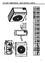
Page 13: ...13 5 0 UNIT DIMENSION _SON SCROLL UNITS ...
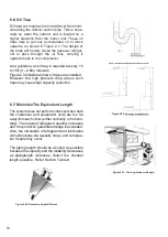
Page 16: ...16 6 5 Things you may do ...
Page 17: ...17 ...
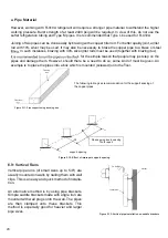
Page 26: ...26 7 4 Liquid Line 7 5 Minimize Bends ...
Page 28: ...28 9 0 REFRIGERANT CHARGE 0 4 0 6 0 3 9 1 Charging by Weight 9 2 Contamination ...
Page 29: ...29 ...
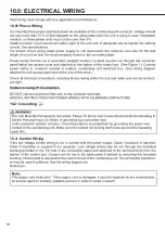
Page 30: ...30 10 2 Grounding 10 3 Control Wiring 10 01 Power Wiring 10 0 ELECTRICAL WIRING ...
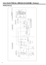
Page 32: ...32 12 0 ELECTRICAL WIRING DIAGRAM Rotary RSON Rotary ...
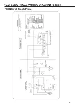
Page 33: ...33 12 2 ELECTRICAL WIRING DIAGRAM Scroll RSON Scroll Single Phase ...
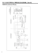
Page 34: ...34 12 1 ELECTRICAL WIRING DIAGRAM Scroll RSON Scroll Three Phase ...
Page 35: ...35 13 0 TROUBLE SHOOTING 13 1 Flow Chart ...
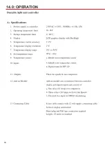
Page 36: ...36 14 0 OPERATION 18 45o C 20 a b a b c ...
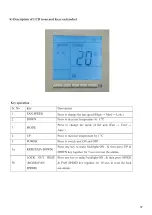
Page 37: ...37 ...
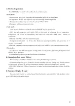
Page 38: ...38 ...
Page 39: ...39 20 ...
Page 40: ...40 ...
Page 41: ...41 14 1 Error Code ...
Page 42: ...Notes ...
Page 43: ...Notes ...

