07
- Model Number
- Serial Number
- Country of Origin
- Rated Voltage and Frequency
- Rated T1 and T3 conditions for:
Rated Current
Rated Power (kW)
Rated Capacity
Rated EER
3.1 Checking Product Received
3.2 Application
There are several factors that the installers must consider:
• Outdoor unit location
• Proper equipment evacuation
• System refrigerant charge
• Indoor unit airflow
• Indoor unit blower speed
• Supply and return air duct design and sizing
• System air balancing
• Diffuser and return air grille location and sizing
3.0: GENERAL
The information contained in this manual has been prepared to assist in the proper installation,
operation and maintenance of the air conditioning system. Improper installation, or installation
not made in accordance with these instructions, can result in unsatisfactory operation and/or
dangerous conditions, and can cause the related warranty not to apply.
Read this manual and any instructions packaged with separate equipment required to make up the
system prior to installation. Retain this manual for future reference.
To achieve optimum efficiency and capacity, the indoor cooling coils listed in the condensing unit
specification sheet should be used.
IMPORTANT:
We recommend replacement of any HVAC equipment that has been subjected to
flooding in order to avoid any risk of injury or harm.
IMPORTANT:
Use all available safety precautions during the installation and servicing of any HVAC
equipment.
The Estimated Annual Energy Consumption of this product is calculated using the following formula:
Upon receiving unit, inspect it for any shipping damage. Claims for damage, either apparent or
concealed, should be filed immediately with the shipping company. Check condensing unit
model number, electrical characteristics and accessories to determine if they are correct and
match the original order from the local distributor.Check system components (evaporator coil,
condensing unit, evaporator blower, etc.) to make sure they are properly matched.
Before installing any air conditioning equipment, a duct analysis of the structure and a heat gain
calculation must be made. A heat gain calculation begins by measuring all external surfaces and
openings that gain heat from the surrounding air and quantifying that heat gain. A heat gain calcula-
tion also calculates the extra heat load caused by sunlight and by humidity removal.
Estimated Annual Energy Consumption = Rated Power (kW) at T1 conditions multi plied by 2700
working hours.
Reference the model nameplate and brand label on the unit for the followinig product information:
Summary of Contents for SON Series
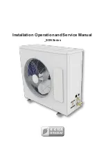
Page 1: ...Installation Operationand Service Manual _SONSeries ...
Page 2: ...02 ...
Page 4: ...1 0 SAFETY INSTRUCTIONS 1 1 WARNINGS 04 ...
Page 9: ...09 4 0 ELECTRICAL PHYSICAL DATA _SON ROTARY ...
Page 10: ...10 6 PHYSICAL AND ELECTRICAL DATA 4 1 TECHNICAL SPECIFICATION _SIN _SON ROTARY UNITS ...
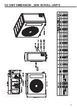
Page 13: ...13 5 0 UNIT DIMENSION _SON SCROLL UNITS ...
Page 16: ...16 6 5 Things you may do ...
Page 17: ...17 ...
Page 26: ...26 7 4 Liquid Line 7 5 Minimize Bends ...
Page 28: ...28 9 0 REFRIGERANT CHARGE 0 4 0 6 0 3 9 1 Charging by Weight 9 2 Contamination ...
Page 29: ...29 ...
Page 30: ...30 10 2 Grounding 10 3 Control Wiring 10 01 Power Wiring 10 0 ELECTRICAL WIRING ...
Page 32: ...32 12 0 ELECTRICAL WIRING DIAGRAM Rotary RSON Rotary ...
Page 33: ...33 12 2 ELECTRICAL WIRING DIAGRAM Scroll RSON Scroll Single Phase ...
Page 34: ...34 12 1 ELECTRICAL WIRING DIAGRAM Scroll RSON Scroll Three Phase ...
Page 35: ...35 13 0 TROUBLE SHOOTING 13 1 Flow Chart ...
Page 36: ...36 14 0 OPERATION 18 45o C 20 a b a b c ...
Page 37: ...37 ...
Page 38: ...38 ...
Page 39: ...39 20 ...
Page 40: ...40 ...
Page 41: ...41 14 1 Error Code ...
Page 42: ...Notes ...
Page 43: ...Notes ...

