Rely on Ruud.™
16
Wiring Diagram/Application Guidelines
UA17 Series
Conventional Thermostat Wiring
W2
W1
C
G
(-)HPN Air
Handler
Y1
Typical Two-Stage Thermostat
(-)ARL
Condensing
Unit
Y2
C
R
Y2
Field Installed
Line Voltage
-
WIRING INFORMATION
Factory Standard
-
ODD
R
Y1
Y2 G
W2
R
Y1
C
L
Y
Y/BL
R
BR
W/R
W1
*
FIGURE
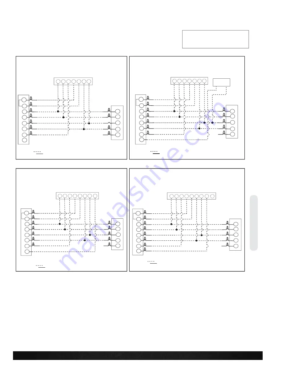
TYPICAL 2-STAGE THERMOSTAT: CONDENSING UNIT WITH
ELECTRIC HEAT
FIGURE 4
TYPICAL TWO-STAGE THERMOSTAT: CONDENSING UNIT WITH
ELECTRIC HEAT USING A HUMIDISTAT FOR DEHUMIDIFICATION*.
W2
W1
C
G
(-)HPN Air
Handler
Y1
Typical Two-Stage Thermostat
(-)ARL
Condensing
Unit
Y2
C
R
Y2
Field Installed
Line Voltage
-
WIRING INFORMATION
Factory Standard
-
ODD
R
Y1
Y2 G
W2
R
Y1
C
L
Y
Y/BL
R
BR
W/R
Humidistat
W1
*
FIGURE 5
TYPICAL TWO-STAGE THERMOSTAT: CONDENSING UNIT WITH
ELECTRIC HEAT USING A TWO-STAGE THERMOSTAT WITH
DEHUMIDIFICATION*
W2
W1
C
G
(-)HPN Air
Handler
Y1
Typical Two-Stage Thermostat
(-)ARL
Condensing
Unit
Y2
C
R
Y2
Field Installed
Line Voltage
-
WIRING INFORMATION
Factory Standard
-
ODD
R
Y1
Y2 G
W2
R
Y1
C
L
Y
Y/BL
R
BR
W/R
DHM
W1
*
W2
W1
C
G
(-)HPN Air
Handler
Y1
Typical Two-Stage Thermostat
(-)ARL
Condensing
Unit
Y2
C
R
Y2
Field Installed
Line Voltage
-
WIRING INFORMATION
Factory Standard
-
ODD
R
Y1
Y2 G
W2
R
Y1
C
L
Y
Y/BL
R
BR
W/R
DHM
L
W1
*
FIGURE 6
CONDENSING UNIT WITH ELECTRIC HEAT USING A TWO-STAGE
THERMOSTAT WITH DEHUMIDIFICATION*
WIRE COLOR CODE
BK – BLACK
G – GREEN
PR – PURPLE Y – YELLOW
BR – BROWN GY – GRAY
R – RED
BL – BLUE
O – ORANGE
W – WHITE
*See Section 5.11 for proper DIP switch selection.
The following figures show the typical wiring diagrams with (-)HPN air handler and (-)ARL con-
densing unit. Cooling and heat pump airflows may need to be adjusted for homeowner comfort
once the system is operational.
*If maximum outlet temperature rise is desired, it is recommended that W1 and W2 be jumpered together.
3
Application Guidelines
1. Intended for outdoor installation with free air inlet and outlet. Outdoor fan external static pressure available is less than 0.01 -in. wc.
2. Minimum outdoor operation air temperature for cooling mode without low-ambient operation accessory is 55°F (12.8°C).
3. Maximum outdoor operating air temperature is 125°F (51.7°C).
4. For reliable operation, unit should be level in all horizontal planes.
5. Use only copper wire for electric connections at unit. Aluminum and clad aluminum are not acceptable for the type of connector
provided.
6. Do not apply capillary tube indoor coils to these units.
7. Factory – supplied filter drier must be installed.
Non-communicating Thermostat Wiring Diagrams

