background image

Rely on Ruud.™

4

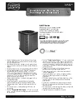
The UA17 is our EcoNet Enabled 17 SEER Two-Stage Air Condi-
tioner and is part of the Ruud Air Conditioner product line that
extends from 13 to 20 SEER. This highly featured and reliable air
conditioner is designed for years of reliable, efficient operation
when matched with Ruud indoor aluminum evaporator coils and
furnaces or air handler units with aluminum evaporators.
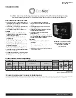
The UA17 is exclusively designed to operate with the EcoNet
Smart Home System. Developed by Ruud, The EcoNet Smart
Home System allows homeowners to manage select high-
efficiency, EcoNet Enabled air conditioners, heat pumps, gas
furnaces, air handlers and water heaters from anywhere.
EcoNet Enabled products in a home are connected through
standard HVAC wiring; then, contractors have the option of
adding an EcoNet WiFi kit (

) so the homeowner can access

everything remotely through a free mobile app or mobile-friendly
website. The Control Center (

) acts as both a thermostat for

the heating and cooling system, and a remote control for con-
nected water heaters.

The EcoNet Smart Home  System is the first integrated system
for a home’s Heating, Cooling and Water Heating equipment –
allowing homeowners to manage the products that consume up
to 65% of their home’s energy. EcoNet sets Ruud, our distributor
and contactor customers apart in the industry with a unique,
advanced and efficient technology solution.

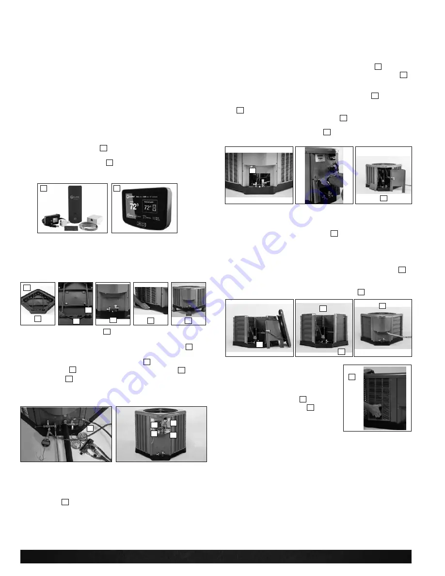
Our unique composite base (

) reduces sound emission, elimi-

nates rattles, significantly reduces fasteners, eliminates corrosion
and has integrated brass compressor attachment inserts (

).

Furthermore it has incorporated into the design, water  manage -
ment features, means for hand placement (

) for unit maneuver-

ing, screw trays (

) and inserts for lifting off unit pad. (

)

Service Valves (

) are rigidly mounted in the composite base

with 3" between suction and discharge valves, 4" clearance
below service valves and a minimum of 5" above the service
valves, creating industry leading ease of installation. The minimum

27 square-inches around the service valves allows ample room
to remove service valve schrader prior to brazing, plenty of
clearance for easy brazing of the suction and discharge lines to
service valve outlets, easy access and hookup of low loss refrig-
erant gauges (

), and access to the service valve caps for

opening. For applications with long-line lengths up to 250 feet
total equivalent length, up to 200 feet condenser above evapora-
tor, or up to 80 feet evaporator above condenser, the long-line
instructions in the installation manual should be followed.

Controls are accessed from the corner of the unit by removing
only two fasteners from the control access cover, revealing the
industry’s largest 15" wide and 14" tall control area (

). With all

this room in the control area the high voltage electrical whip (

)

can easily be inserted through the right size opening in the
 bottom of the control area. Routing it leads directly to contractor
lugs for connection. The low voltage control wires (

) are easily

connected to the units low voltage wiring. If contactor or capaci-
tor (

) needs to be replaced there is more than adequate space

to make the repair. The service window (

) can be removed by

removing two screws, to access the high and low pressure
switches and view interior of unit. (

) (High and low pressure is

standard on UA17 models).

If in the rare event, greater access is needed to internal compo-
nents, such as the compressor, the entire corner of the unit can
be removed along with the top cover assembly to have unprece-
dented access to interior of the unit (

). Extra wire length is

incorporated into each outdoor fan and compressor so top
cover and control panel can be positioned next to the unit. With
minimal effort the plug can be removed from the compressor
and the outdoor fan wires can be removed from the capacitor to
allow even more uncluttered access to the interior of the unit (

).

Outdoor coil heights range from as short as 35" to 51". Disas-
sembly to this degree and complete reassembly only takes a first
time service technician less than 10 minutes. (

)

All units utilize strong formed louver
panels which provide industry leading
coil protection. Louver removal for coil
cleaning is accomplished by removing
one screw and lifting the panel out of 
the composite base pan. (

) All UA17

units utilize single row coils (

) making

cleaning easy and complete, restoring
the performance of the air conditioner
back to out of the box performance
levels year after year. 

3

4

5

6

9

8

7

1

2

10

11

12

13

14

15

16

17

17

19

18

Features & Benefits
UA17 Series

Introduction to UA17 Air Conditioner

3

6

6

5

7

4

10

13

11

12

15

14 

18

16

20

17

9

19

8

2

1

Summary of Contents for UA1724A

Page 1: ...and reliability Modern cabinet aesthetics increased curb appeal with visu ally appealing design Curved louver panels provide ultimate coil protection enhance cabinet strength and increased cabinet rig...

Page 2: ...on 7 8 General Data Electrical Data 9 Accessories 10 Weighted Sound Power 10 Smart Home Systems 11 12 Unit Dimensions 13 Clearances 14 Wiring Diagrams 15 16 Application Guidelines 15 16 Refrigerant Li...

Page 3: ...release louver panel design No fasteners to remove along bottom Optimized Venturi Airflow Single row condenser coil Powder coated paint Rust resistant screws QR code External gauge ports Service trays...

Page 4: ...and hookup of low loss refrig erant gauges and access to the service valve caps for opening For applications with long line lengths up to 250 feet total equivalent length up to 200 feet condenser abov...

Page 5: ...it has been ran in cooling operation at 95 F and 82 F and sound ratings for the UA17 range from as low as 72 3 dBA to 76 7 dBA All units have been ship tested to assure units meet stringent over the r...

Page 6: ...a home s Heating Cooling and Water Heating systems and is required to operate an EcoNet Enabled Heating Cooling system in a fully communicating mode WiFi Kit for Heating and Cooling Systems The WiFi k...

Page 7: ...30 30 000 8 79 kW 36 36 000 10 55 kW 42 42 000 12 31 kW 48 48 000 14 07 kW 60 60 000 17 58 kW A 1st Design J 1ph 208 230 60 C 3ph 208 230 60 D 3ph 460 60 1 Single stage 2 Two stage V Inverter P Pisto...

Page 8: ...kW 125 125 000 37 kW 150 150 000 44 kW 3 up to 3 ton 4 2 1 2 to 4 ton 5 3 1 2 up to 5 ton 14 14 17 17 5 21 21 24 24 5 M Multi D Down Z Down zero clearance down flow X Low Nox S Standard A 1st Design...

Page 9: ...850 820 646 825 watts 112 112 132 113 Shipping weight lbs 200 209 297 298 Operating weight lbs 193 202 290 291 Electrical Data Line Voltage Data Volts Phase Hz 208 230 1 60 208 230 1 60 208 230 1 60 2...

Page 10: ...Solenoid 24 VAC 50 60 Hz Solenoid Valve 200RD2T3TVLC 200RD2T3TVLC 200RD3T3TVLC 200RD3T3TVLC Solenoid Coil 61 AMG24V 61 AMG24V 61 AMG24V 61 AMG24V Liquid Line Solenoid 120 240 VAC 50 60 Hz Solenoid Va...

Page 11: ...Module EcoNet app for smart phones and tablets Warranty 5 Year limited warranty from date of installation Source Department of Energy When compared to non programmable thermostats Source ENERGY STAR f...

Page 12: ...tus Internet Connection Status WLAN SETUP factory reset button WiFi Kit Components EcoNet WiFi Module Installation Instructions V Power Adapter Junction Box 24 Port to Port Connection Cable 1 x 2 Doub...

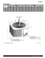
Page 13: ...HES mm INCHES mm INCHES mm INCHES mm INCHES mm UA1724 35 889 33 75 857 33 75 857 36 75 933 36 38 924 36 38 924 UA1736 39 990 33 75 857 33 75 857 40 75 1035 36 38 924 36 38 924 UA1748 51 1295 35 75 908...

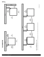
Page 14: ...304 8 6 152 4 24 609 6 Service 24 609 6 Service 24 609 6 Service 18 457 2 WALL WALL WALL WALL NOTE NUMBERS IN mm CLEARANCES IMPORTANT When installing multiple units in an alcove roof well or partially...

Page 15: ...an external static pressure available is less than 0 01 in wc 2 Minimum outdoor operation air temperature for cooling mode without low ambient operation accessory is 55 F 12 8 C 3 Maximum outdoor oper...

Page 16: ...INFORMATION Factory Standard ODD R Y1 Y2 G W2 R Y1 C L Y Y BL R BR W R DHM L W1 FIGURE 6 CONDENSING UNIT WITH ELECTRIC HEAT USING A TWO STAGE THERMOSTAT WITH DEHUMIDIFICATION WIRE COLOR CODE BK BLACK...

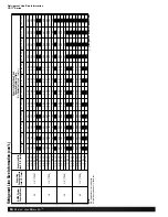
Page 17: ...67 30 9 14 7 16 11 12 25 7 62 50 15 24 75 22 86 75 22 86 75 22 86 75 22 86 70 21 34 70 21 34 70 21 34 65 19 81 65 19 81 60 18 29 1 2 12 71 25 7 62 50 15 24 75 22 86 80 24 38 80 24 38 80 24 38 80 24 38...

Page 18: ...0 96 0 96 0 95 0 95 7 8 22 23 1 01 1 00 1 00 1 00 0 99 0 99 0 99 0 99 0 99 0 99 0 99 0 99 1 25 4 1 01 1 01 1 01 1 00 1 00 1 00 1 00 1 00 1 00 1 00 1 00 1 00 1 1 8 28 58 N R N R N R N R N R N R N R N...

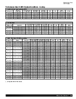
Page 19: ...6 26000 7 6 10000 2 9 17 00 13 00 1075 507 3 8232069 RCF6021SEAM 36000 10 6 26000 7 6 10000 2 9 17 00 13 00 1075 507 3 8232078 UA1736AJ2 U802VA075317ZSA RCF3621MEAM 36000 10 6 26000 7 6 10000 2 9 17...

Page 20: ...0000 2 9 17 00 13 00 1050 495 5 8232084 UA1736AJ2 U96VA0852521MSB RCF3621MEAM 36000 10 6 26000 7 6 10000 2 9 16 50 13 00 1075 507 3 8232076 RCF6021SEAM 36000 10 6 26000 7 6 10000 2 9 17 00 13 00 1075...

Page 21: ...17 1 1 2 TO 5 NOMINAL TONS Fans Condenser fan will be direct drive propeller type discharging air upward Condenser fan motors will be totally enclosed 1 phase type with class B insulation and permanen...

Page 22: ...e within the applicable period stated in accordance with the terms of the limited warranty For complete details of the Limited and Conditional Warranties including applicable terms and conditions cont...

Page 23: ...Rely on Ruud 23 Notes UA17 Series...

Page 24: ...ud Heating Cooling Water Heating P O Box 17010 Fort Smith Arkansas 72917 www ruud com In keeping with its policy of continuous progress and product improvement Ruud reserves the right to make changes...

Reviews: