11
2009-03
RVR
Energy Technology Experts
Operational mode – Modulating, double effect position
Modulating, automatic exchange between low and high out-
put.
Output low/high: 15/20 kW.
The burner switches to high output after being in low output
mode for 20 minutes.
Circuit breaker:
Temperature controlled
Boiler temperature regulation via the burner, with modulating
operation. The burner's temperature regulation controls the
boiler temperature with an engagement differential of ±8°C
relative to set temperature. The temperature setting is carried
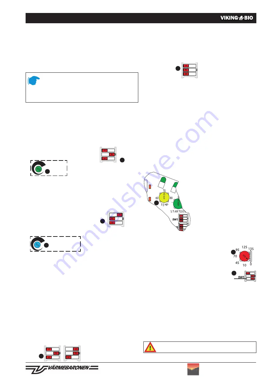
out on the circuit board, point 21.
Boiler temperature indicator, accessory, must be connected to
the burner. Switches SW1/1 and SW1/2 are set to modulating
mode according to above diagram.
In idle mode, the burner detects the sudden drop in tempera-
ture, which can arise in a "heat exchange boiler" with hot
water provision. The burner then starts before the temperature
has dropped to its normal start value.
The burner switches automatically to high output mode if has
been in low output mode for 20 minutes.
Temperature control is also suitable when the burner is mount-
ed in a wood burning boiler with accumulator tanks.
The burner should be electrically engaged according to "Boiler tempera-
ture control via burner", see page 6.
Where the burner is governed by an boiler thermo-
stat, all its indicators will start to fl ash if it is
set at a lower temperature than the temperature
setting on the burner itself.
In the event that the boiler thermostat breaks
down whilst in operation, pellet feeding is ter-
minated, the burner switches to the cooling
phase and then closes down with all its indi-
cators fl ashing. Restart requires a reset
of the alarm – see Resetting the alarm
page 16. The boiler's thermostat must be
set at the highest value, the temperature
setting on the burner is set to at least 10-
15°C lower than this.
Start delay
With switch SW1/3 in the "ON" position, a start
delay of 0-135 minutes is obtained, as per
the setting at switch 25. Using this function
extends the burner's longevity, which raises
effi ciency levels. This function can be used in
all operational modes, but is not suitable for
boilers where hot water is provided via a heat
exchanger.
Flue air fl ow
To ensure good operational economy, the fl ue air fl ow should
be <5 Pa, which is adjusted using the boilers fl ue gas damper.
In certain circumstances, the draught can be diffi cult to set
correctly. Flue air fl ow affects the time it takes for the burner to
ignite. The prevailing conditions are input with switch SW2/2,
see point 23 on page 9. Please see also the section – The fl ue
and the contrafl ow hatch on page 10.
Switch SW2/2:
OFF: Normal position draught ±0 to -15 Pa.
ON:
High draught: draught -15 to -20 Pa.
General
Because of the the screw's uneven feed ratio during the fi rst day of use,
the adjustments should be checked after approx. a week's cycle.
Adjustments are always made in high output mode, delivery settings.
Adjustments must be carried out using a fl ue gas analysis instrument.
Authorised soot count on testing is 1- 3.
Adjustments
Please follow the points below in exact sequence when mak-
ing adjustments:
1. Checking settings.
Please check that the settings have the values shown in the
diagrams on page 9, points 22, 23, 24 and 26.
2. Adjustments – High output
A.
Switches set according to dia-
gram:
B.
Start the burner and allow it to
run for approx.
10 minutes.
Carry out a
CO
2
measurement.
Adjust at "Fuel", nr 24. Where
CO
2
value is:
Too low, increase "Fuel".
Too high, reduce "Fuel".
Due to variations, the test should be repeated several
times.
3. Adjustments Low output
A.
With the burner running, the switches
are set according to diagram:
B.
Allow the burner to burn for approx. 5
minutes, before carrying out a soot test.
Settings for fuel amounts
must not be changed.
Carry out a
CO
2
measurement.
Adjust with "Air LOW Output",
nr 26.
Where
CO
2
value is:
Too low, reduce "Air LOW out-
put".
Too high, increase "Air LOW
output".
Due to variations, the test should be repeated several
times.
4. The burner has now been adjusted.
Now choose the operational mode under which the the
burner is going to operate, see also page 9.
Operational mode – High output mode, single effect
position
Output: 20 kW
Back pressure in the boiler chamber: 0- 15 Pa
Circuit breaker:
Adjustments
Use only the setting which applies for the prevailing condi-
tions.
21
24
26
SW1/1: ON
SW1/2: OFF
23
SW1/1: OFF
SW1/2: OFF
23
SW1/1: OFF
SW1/2: ON
23
23
25
SW1/3
Correct adjustments are important so as to ensure fuel burn-
ing effi ciency, a high level of energy effi ciency, low discharge
of substances that may harm the environment, and also
for the longevity of those parts of the burner which come
into contact with fl ames. Optimum adjustments can only be
achieved using fl ue gas analysis instruments.
SW1/1: OFF
SW1/2: ON
SW1/1: ON
SW1/2: ON
alt.
23
Fuel
Air Low Ouput


