6
2009-03
RVR
Energy Technology Experts
1
2
3
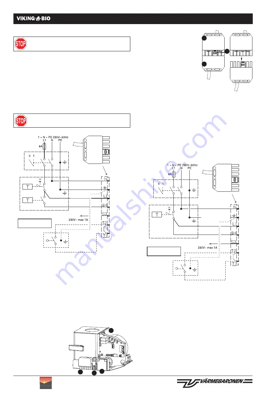
The plug, 3, is pressed into the
socket part, 1, which sits on the
burner, until the catch on the push
button, 2, grips and locks the the
plug into position.
When decoupling, the current to
the burner must fi rst be switched
off, after which the push button
is pushed in at the same time as
the plug is withdrawn from the
socket.
Safety switch
A safety switch should be mounted wherever the
boiler hatch can be opened without the need for
a special tool. Alternatively, safety regulations can be observed
by making the tube between the screw feeder and burner so
short that it has to be detached from the burner before the
hatch can be opened.
Boiler temperature control via burner
Where the burner is controlled by boiler temperature, a temper-
ature indicator must be included – accessory. The temperature
indicator is equipped with a contact which is connected to the
corresponding contact on the burner, see point 3 in the section
Connections/fi ttings on the burner.
Where the burner is not covered by a "normal" boiler thermo-
stat, the confi guration can be set as per the diagram below.
An overheat device must always be included.
Allowing the burner to control boiler temperature is advanta-
geous when the burner is mounted on an boiler using a heat
exchanger for hot water services. The burner's temperature
regulation has a large differential, ±8°C, relative to set tem-
peratures, which reduces start and stop times and increases
operational life.
The temperature indicator for boiler temperatures should pref-
erably be placed in a pocket tube, or high up in the body of the
boiler under the isolator. In a boiler where hot water is provided
via a heat exchanger, the indicator should be placed in such
a way that it picks up the return fl ow, though not on the heat
exchanger's return pipe.
Where no pocket tube is available for the indicator, it can be
glued onto the body of the boiler using a double bond epoxy
resin. It is important that the indicator has good thermal con-
tact so that temperature regulation is both accurate and stable.
In the Värmebaronen Star heat exchanging boiler, the tempera-
ture indicator is placed in the pocket tube, which can be found
on the left hand side, behind the foldable automatics cabinet.
Electrical connections
This page shows how to install electrical connections for
Värmebaronen boiler.
The installation must be carried out according to current gen-
eral and local regulations, including those stipulations covering
any accessory equipment used in the electrical confi guration.
The burner must be covered by a multi pole switch, 6A fuse.
The confi guration chosen depends on the boiler upon which
the burner is mounted, and whether this boiler already has
electrical equipment in place. The confi guration must, however,
follow the electrical diagram below.
Wire connections to burner
PLEASE NOTE! 230V~ on all leads
L1
: black, feed for the burner via an overheating guard.
B4
: brown, is connected to the boiler thermostat.
S3
: grey, alarm signal from the burner.
T1
: to safety cut-out on boiler hatch, when used.
T2
: from safety cut-out on boiler hatch, when used.
On delivery, the T1 – T2 terminals are coupled together.
Connections/fi ttings on the burner
1. Temperature delimiter downpipe
2. Seven polar contact point
3. Temperature indicator
4. Screw feeder
Please check that the contact
points are pressed together prop-
erly.
Electrical installation
2
3
1
4
Jumper wire T1
-T2 is removed
when the
safety switch is
attached.
THERMOSTAT
OVERHEAT DEVICE
Jumper wire T1
-T2 is removed
when the
safety gate is
attached.
The electrical installation must be carried out according to
the IEE regulations, under the guidance of a qualifi ed electri-
cal installer.
Phase feeding to the burner must always be covered by an
overheating guard and the control phase by a thermostat.
Burner Switch
Double Thermostat
Please Note!
230V on all leads!
Safety Switch
Alarm
Blue
Yellow/Green
Black
Brown
Grey
Feed
Burner Switch
Overheating Guard
Please Note!
230V on all leads!
Safety switch
Alarm
Blue
Yellow/Green
Black
Brown
Grey
Feed


