background image

MOBILEMULE™ 4 CHANNEL MOBILE DVR WITH

GPS TRACKING AND LIVE VIDEO OPTIONS

RVS-6200

Instruction Manual

VEHICLE SAFETY - 
IT'S ALL WE DO.

TM

Summary of Contents for MOBILEMULE RVS-6200

Page 1: ...MOBILEMULE 4 CHANNEL MOBILE DVR WITH GPS TRACKING AND LIVE VIDEO OPTIONS RVS 6200 Instruction Manual VEHICLE SAFETY IT S ALL WE DO TM...

Page 2: ...l setting 18 5 3 2 Video setting 18 5 3 3 Record setting 19 5 3 4 Alarm control 19 5 3 5 Record setting 20 5 3 6 Monitor display 21 Advanced options 5 4 1 System upgrade 22 5 4 2 Restore default 23 5...

Page 3: ...t to repair disassemble DVR Please contact our tech team with any problems The initial password is NULL DVR Power Range DC6V DC36V Unplug from power completely if you are not using system for an exten...

Page 4: ...4 2 Product Specification...

Page 5: ...L Level LED Indication PWR RUN Disk lock 1 Debug port 1 Function extention GPS BD Support detecting antenna Plug in Unplug Short circuit 3G 4G Supports CDMA EVDO GPRS WCDMA FDD LTE TDD LTE WIFI 802 11...

Page 6: ...ripon Power LED light on when power works normally PWR abnormally Alarm LED light on when device works Indicator LED LOCK ON Switch lock remove the card Note remove the HDD on ON posion Light on when...

Page 7: ...7 USB DEBUG SD1 The rst SD card commonly used USB port to plug in Mouse 8 9 10 Interface Serial number Parameter Descripon Indicator LED Debug window 1 2 3 4 5 6 7 3 2 Back Panel Interface...

Page 8: ...D 12V pin 2 is GND pin 3 is audio input pin 4 is video input AV2 AV3 AV4 Antenna 5 3G WIFI GPS 3G antenna interface 6 WIFI 7 GPS Network 2 VGA VGA connection Alarm I O interface 4 I O Input vehicle sp...

Page 9: ...umber Mark on the cable end 12V power supply for video camera 1 12V Ground wire 2 GND Audio pickup input wire 3 A IN Video input wire 4 V IN Table 5 3 3 2 Power Cable Picture 4 Power input cable pictu...

Page 10: ...d and black ground connect to the vehicle directly The yellow cable is connected to ignition The DVR will start when the vehicle is turned on and have a delayed shut out when the vehicle is turned off...

Page 11: ...ice has an interface with 4 alarm inputs and 2 alarm outputs These alarms can be connects to a variety of triggers The principle diagram of brake detection is as shown below When the brake pedal is pr...

Page 12: ...etecon Picture 8 Alarm principle diagram 12 The alarm outputs have a maximum current capability of 200MA If you want to drive a device with higher current requirement you must connect external relay S...

Page 13: ...Please cross check the list below with the device and accompanying accessories Item Quantity Notes MDVR 1 Digital LCD monitor 1 optional CD 1 GPS antenna 1 Wi antenna 1 optional 3G 4G antenna 1 option...

Page 14: ...Picture 9 SIM Card SD card installaon diagram Picture 10 SIM Card SD card installaon diagram 2 14 SIM SD Open the DVR to see both the SIM and SD card slots...

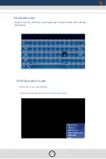
Page 15: ...Keyboard Input System can use numbers lower uppercase English letters and Chinese Characters DVR Operation Guide Right click to open login interface Input Username password click OK to login to the me...

Page 16: ...16 5 1User login Default Username is admin with no password...

Page 17: ...17 5 2 Video Preview 5 3 System Setting...

Page 18: ...10 18 5 3 1 General Setting 5 3 2 Video Setting...

Page 19: ...19 5 3 3 Record Setting 5 3 4 Alarm Control...

Page 20: ...20 5 3 5 Motion Detection Camera Settings Set CH Trigger Delay Time Distance Grid Line...

Page 21: ...21 5 3 6 Monitor display The grid lines are adjustable move the purple points After adjustment right click the mouse to save settings...

Page 22: ...5 4 Advanced Options 5 4 1 System Upgrade Copy the upgrading file to the root directory of the USB disk Then re power on the device it will upgrade automatically 22...

Page 23: ...to different monitor Copy Configuration File 1 Click Backup 2 Disconnect Mouse 3 Connect USB Device 4 Will Display Congratulations Action Succedded Copy Configuration File 1 Click Resume 2 Disconnect...

Page 24: ...24 5 4 4 Username 5 4 5 Encode Overview...

Page 25: ...25 5 5 System Info...

Page 26: ...26 5 6 File Backup 5 7 Disk Management Disk need to be formated in the device when using it for the first time If the disk was not detected by the device confirm the device is locked...

Page 27: ...27 5 8 Vehicle Settings 5 8 1 Basic Info If you want to change the vehicle ID number please login with super password szmzkj...

Page 28: ...5 8 2 G Sensor 5 8 3 Power Management 28...

Page 29: ...5 8 4 Wi Fi Setting 5 8 4 1 Network Status 29 The device can save 6 WiFi ESSID Access Points Turn on WiFi and save as show below...

Page 30: ...Module Type detected Putting in the wireless account will automatically connect it If it does not connect consult your SIM card carrier or search on Internet to make sure you put the correct paramete...

Page 31: ...31 5 9 Playback 5 8 6 Network Settings We have set it with our server in factory if use different server please set your server s IP or Domain the Port should be same with your server setup...

Page 32: ...6 Playing video files are computer has obvious halt A Please confirm speed of SD card 7 Recording time is too short A Excessive le fragments generate due to repeated usage Please format the SD card co...

Page 33: ...e is not set B Video recorder not reset after delay time was set A Audio of each channel takes up roughly 14M per hour B Video takes up roughly 00 220M CIF 200 300M HD1 and 400 600M D1 per hour C The...

Page 34: ...If you have any questions about this product contact Rear View Safety Inc 1797 Atlantic Avenue Brooklyn NY 11233 800 764 1028 VEHICLE SAFETY IT S ALL WE DO TM...

Reviews: