RVS Systems
12
INST
ALL
ATION
AND
WIRE
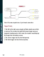
FIGURE 2.1
Red to ACC +12
Left trigger wire
Left camera
Right camera
Backup camera
Front camera
Black to GND
Right trigger wire
Reverse trigger line
Front trigger line
Note: All camera inputs have a 5 pin female connection
Trigger Priority
1. The left or the right camera inputs will take priority over all oth-
er cameras. This is unless the right/left/reverse trigger wires are
triggered simultaneously. In this event, the monitor would display
the image from the backup camera.
2. The reverse trigger wire has the third priority.
3. The front trigger wire has the least priority.


