background image

RVS Systems

8

INST

ALL

ATION

 GUIDE

Replacement Monitor

The mirror monitor replaces the existing car mirror. Carefully remove 
the mirror off the “pin”. Slide the replacement mirror on to the pin and 
secure it with the screw provided (already in the screw hole).Differ-
ent cars have different brackets. Depending on your vehicle make and 
manufacturer. There are many methods to remove the original rear-
view mirror, however, please don’t force the mirror off the bracket.
The manufacturer will not be responsible for damage caused to your 
car by incorrect mirror installation. Figure 1.1

Camera & Cable

Be sure to position the cable properly. The aviation camera cable uses 
aircraft grade connectors which means the camera cable can be ex-
posed to all weather elements. Do not run the cable over sharp edges, 
do not kink the cable and keep away from HOT and rotating parts.
Fasten all cables and secure all excess cable. Connect camera to the 
camera extension cable which runs inside the vehicle. Figure 1.2

Summary of Contents for RVS-218637

Page 1: ...ReverseWithConfidence 1 G Series 4 Channel Backup Camera System RVS 218637 Instruction Manual...

Page 2: ...tion 04 06 Before Beginning Installation 07 Installation Guide 08 09 Adjustable Grid Line 10 Installation and Wire 11 13 System Introduction 14 15 Monitor Specifications 16 Camera Specifications 17 Wa...

Page 3: ...intended to be installed as a supplement aid to your standard rear view mirror that already exists in your vehicle The Backup Camera System should not be used as a substitute for the standard rear vi...

Page 4: ...mustuseit properly Use of this system is not a substitute for safe proper or legal driving Neverbackupwhilelookingatthe monitor alone You should always check behind and around the vehi cle when backin...

Page 5: ...immediately Wherethepowercablemaytouch a metal case cover the cable with friction tape A short circuit or disconnected wire may cause a fire While installing the Rear View System be careful with the w...

Page 6: ...OR ANY DIRECT OR CONSEQUENTIAL DAMAGES OF ANY NATURE OR LOSSES OR EXPENSES RESULTING FROM ANY DEFECTIVE PRODUCT ORTHE USE OF ANY PRODUCT SAFETY INFORMATION Ifyouhavequestionsaboutthisproduct contact R...

Page 7: ...y components Werecommenddoingabenchmarktestbeforeinstallation toinsurethatallcomponentsareworkingproperly Step 1 Choose the monitor and camera locations Step 2 Install all cables in vehicle when neces...

Page 8: ...ew mirror however please don t force the mirror off the bracket The manufacturer will not be responsible for damage caused to your car by incorrect mirror installation Figure 1 1 Camera Cable Be sure...

Page 9: ...dditional camer as connect to the corresponding input Figure 2 1 Figure 2 2 PrecautionsforuseofMirrorMonitor I The Mirror Monitor is made of glass Do not subject it to a mechanical shock by dropping i...

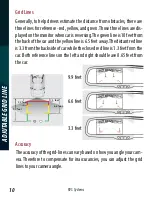
Page 10: ...backofthecarandtheyellowlineis6 5feetaway Thedistantredline is3 3fromthebacksideofcarwhiletheclosedredlineis1 3feetfromthe car Both reference lines on the left and right should leave 0 65 feet from th...

Page 11: ...ReverseWithConfidence 11 INSTALLATION AND WIRE FIGURE1 1 FIGURE1 2...

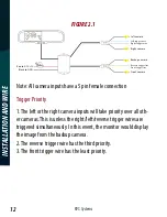
Page 12: ...ote All camera inputs have a 5 pin female connection Trigger Priority 1 The left or the right camera inputs will take priority over all oth er cameras This is unless the right left reverse trigger wir...

Page 13: ...ReverseWithConfidence 13 INSTALLATION AND WIRE FIGURE2 2...

Page 14: ...stems 14 SYSTEM INTRODUCTION Remote Introduction Up Clockwise Down Right Left Adjust grid line Counterclockwise Press the button to toggle L R gridlines Remote control Rotate gride line Remote Introdu...

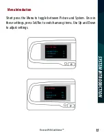
Page 15: ...CALE ON 10S OFF SCREEN OFF PRESET Menu setting guidance Short press you can switch among PICTUR out When you enter PICTURE press to s setting is the same as explains above PICTURE BRIGHTNESS 50 50 50...

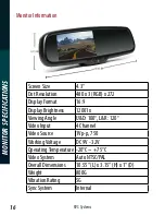
Page 16: ...272 Display Format 16 9 Display Brightness 12001x Viewing Angle U D 100 L R 120 Video Input 4 Channel Video Source 1Vp p 750 WorkingVoltage DC 9V 32V OperatingTemperature 20 C 75 C Video System Auto N...

Page 17: ...iewing Angle 170 Weatherproof Rating IP68 NightVision Yes Usable Illumination 0 5 Lux Power Source DC 12V 24V 10 S N Ratio 48dB Electronic Iris 1 50 160 1 100 000sec Cable Length From Camera 5 8 Video...

Page 18: ...THE RVS SYSTEMS INC SYSTEM AFTER PARTIAL FAILURE OR USEWITH IMPROPER ACCESSORIES WARRANTY PERFORMANCE DURINGTHE ABOVEWARRANTY PERIOD SHOULDYOUR RVS SYSTEMS PRODUCT EXHIBIT A DEFECT IN MATERIAL ORWORKM...

Page 19: ...ER SAFELY REARVIEW SAFETY AND OR ITS AFFILIATES SHALL HAVE NO RESPONSIBILITY OR LIABILITY FOR DAMAGE AND OR INJURY RESULTING FROM ACCIDENTS OCCURRING WITH VEHICLES HAVING SOME OF RVS SYSTEMS PRODUCTS...

Page 20: ...RVSSystems 20 If you have any questions about this product contact RVSSystems Inc 1797AtlanticAvenue Brooklyn NY11233 800 764 1028 BetterCameras BetterService IT SOURGUARANTEE...

Reviews: