Installation, operating and maintenance manual SKIT/S-DEB
3rd print version
page 23
3 – Design and function
RWO GmbH
●
Marine Water Technology
●
Bremen
●
Germany
Issue 2014-04-10
Type
Pos.
DE
B
0.
1
DE
B
0.
25
DE
B
0.
50
DE
B
1.
00
DE
B
1.
50
DE
B
2.
5
DE
B
5.
0
DE
B
10.
0
4 (DN)
15
20
20
20
20
25
25
40
5 (DN)
15
15
15
15
15
20
20
32
6
(inch)
¼“
¼“
¼“
¼“
¼“
¼“
¼“
¼“
15
(DN)
15
15
15
15
15
15
20
25
22
(DN)
15
25
25
25
32
32
50
65
23B(D
N)
20
20
20
25
32
32
40
50
25A
(inch)
¼“
¼“
¼“
¼“
¼“
¼“
¼“
¼“
25B
(inch)
¼“
¼“
¼“
¼“
¼“
¼“
¼“
¼“
27
(inch)
1“
1“
1“
1“
1“
1“
1“
1 ½“
27A
(inch)
½“
½“
½“
½“
½“
½“
1“
1“
55A
(DN)
20
20
20
25
32
32
40
50
55B
(DN)
20
20
20
25
32
32
40
50
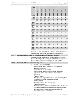
Tab. 7 Pipe connections
Connect all pipe connections in the specified dimensions.
Fit the piping stress-free and leak-tight into the unit.
3.15
Operating instructions for programmable oil separator control
Operation of the oil separator control involves 4 buttons.
The backlit display has two lines with 20 characters each.
The operational modes are displayed with 4 LEDs.
Elements of the control and display field
3.15.1
·
On/ Off – main switch 1S1
Switch for the supply voltage of the oily water
separator (on or off)
Switch hand – 0 – Auto 2S3
Switch for the operation mode of the oily water
separator control (manual, zero or automatic
operation).
Position "Hand":
The oily water separator operates independently from
the level in the bilge or bilge water tank.
Position "Zero":
The oil separator does not operate.
Position Automatic
The oil separator starts automatically when the level in
the bilge or bilge water tank switches the upper level
sensor and stops automatically when the level
switches the lower level sensor.


