Installation, operating and maintenance manual SKIT/S-DEB
3rd print version
page 37
6 – Preparation for commissioning
RWO GmbH
●
Marine Water Technology
●
Bremen
●
Germany
Issue 2014-04-10
6.4
Electricity
Note
The voltage on board must be specified during the
order and check for compliance with the label on
the automatic control box before connecting to the
oil separator system.
Incorrect electric connection voltage can destroy
electric components! The voltage on board must be
specified during the order and check for
compliance with the label on the automatic control
box before connecting to the oil separator system.
Incorrect electric connection voltage can destroy
electric components!
All system parts are wired by factory default; they are
controlled and supplied via the automatic control box.
Standard systems operate on 3-phase alternating
current. The supply inlet is pos. 2 (chapter
à
3.1, Cable
inlet: DIN 89280; 1430-W 18; shape K;). The automatic
system is installed in a robust steel housing IP 56 with
MS naval cable screw connections according to DIN
89280 (the max. cable diameter is 18 mm)
6.5
Valve terminal
WARNING
Do not release lines or valves in systems under
pressure!
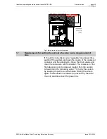
The pneumatic valves are triggered centrally from the
solenoid valve terminal. It is installed in the control box
and thus protected. The valve terminal is equipped with 3
dual solenoid valve inserts (2 x 3/2-way). 5 of those are
used by default, 1 is designed as spare in case a solenoid
valve fails.
Fig. 9 Valve terminal

