background image

16

HEAVY DUTY 

SOD CUTTER

ADJUSTMENTS

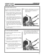
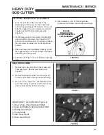
ADJUSTING BLADE ANGLE (PITCH)

1.  Loosen blade angle control locking lever 

F

 and 

move H-frame forward or backward until blade is 
at desired angle of pitch. 

2.  Tighten blade angle control locking lever 

F

.

SIDE ARM

DRIVE

WHEEL

BLADE

BOTTOM

BLADE

ANGLE

(Pitch)

BLADE ANGLE (PITCH)


Under normal operating conditions, blade angle 

is minimal (blade bottom is flat).  In extremely 

hard soil or when cutting with a dull blade, the 
blade may want to ride out of the ground.  It may 
then help to adjust blade angle forward (see 
Adjusting Blade Angle below).  A short trial run 
will indicate what the best blade angle is.

NOTE:  Extreme blade angles put extra stress on 

the side arms.  To reduce stress on the machine, 

operate with the flattest blade angle that gives 

satisfactory results.

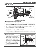
ADJUSTING OPERATOR PRESENCE CONTROL

1.  To adjust operator presence cable, pull clutch 

control handle 

A

 rearward as far as possible. 

2.  Press operator presence handle (right handlebar) 

down as far as possible.

3.  Adjust cable until the pivot arm 

C

 contacts the 

arm extending from the operator presence switch 

B

.

4.  Tighten cable clamp to secure cable. Check for 

proper operation.

Summary of Contents for 544853G

Page 1: ...OPERATOR S PARTS MANUAL MAN 4167007 Rev A 08 2011 544853G HEAVY DUTY SODCUTTER 11HP HONDA 16 544854G HEAVY DUTY SODCUTTER 11HP HONDA 18...

Page 2: ......

Page 3: ...parts needed Schiller Grounds Care Inc service ensures that you continue to receive the best results possible from Schiller Grounds Care Inc products You can trust Ryan replacement parts because they...

Page 4: ...ories or products not approved by Schiller Grounds Care Inc will be considered the responsibility of the individual s or company designing and or making such changes Schiller Grounds Care Inc will vig...

Page 5: ...placement labels and manuals are available from the factory Do not operate machine while under the influence of drugs or alcohol The owner user can prevent and is responsible for accidents or injuries...

Page 6: ...lade stops moving before refueling before making blade adjustment Stop the engine disengage the master clutch and disconnect the spark plug wire s before clearing blockages before checking cleaning or...

Page 7: ...top the engine and allow to cool Do not smoke Refuel outdoors only Use a funnel Do not overfill If fuel is spilled do not attempt to start the engine until the spill is cleaned up and vapors have clea...

Page 8: ...rs in a locked storage place to prevent tampering and to keep children from playing with them Do not store the machine or fuel container near heating appliances with an open flame such as a water heat...

Page 9: ...NK WITH REGULAR GASOLINE 2 PULL CLUTCH LEVER BACK TO DISENGAGED POSITION 3 SET THROTTLE TO 1 2 OPEN POSITION 4 SET CHOKE AND START ENGINE SOD CUTTING INSTRUCTIONS 1 MAKE REQUIRED BLADE ADJUSTMENTS 2 S...

Page 10: ...LOCKING LEVER TIP MACHINE FORWARD AND MOVE CENTER DEPTH CONTROL LEVER TO DESIRED DEPTH LOCK IN POSITION BY ROTATING LOCKING LEVER CLOCKWISE 2 LOOSEN DEPTH STOP LOCKING LEVER AT CENTER OF H FRAME RAISE...

Page 11: ...ey with not be misplaced or lost 5 Remove the two screws and lockwashers from upper rear of gear case A Use those screws and lockwashers to install upper portion of handle Secure the lower end of the...

Page 12: ...M and connect red wire from operator presence control N to the red wires you justdisconnected Figure7 Useziptiestotiedown wire harnes as shown Figure 10 11 Attach the cutting blade H to the side arms...

Page 13: ...ed METERING WHEEL CONTROL LEVER D Raises lowers metering wheel to engage disengage cut off mechanism BLADE DEPTH CONTROL LEVER E Raises or lowers cutting blade BLADE DEPTH CONTROL LOCKING LEVER F Lock...

Page 14: ...illed fuel BEFORE STARTING THE ENGINE 1 Be familiar with the controls how each functions and what each operates 2 Check engine oil level Add oil if necessary following the engine manufacturer s recomm...

Page 15: ...underground utilities Contacting buried utilities could result in a service outage Contacting buried electrical wires could result in electrocution Contacting a buried gas line could result in an expl...

Page 16: ...has traveled past the preset distance When the cut off mechanism is tripped the cut off blade comes down and cuts the sod strip It is normal for the handle to jump slightly when the cut off blade cycl...

Page 17: ...h gauge G and depth control lever D if necessary NOTE Numbers on depth gauge do not necessarily represent thickness of sod being cut The numbers are useful as a reference for making changes CUT OFF BL...

Page 18: ...ground It may then help to adjust blade angle forward see Adjusting Blade Angle below A short trial run will indicate what the best blade angle is NOTE Extreme blade angles put extra stress on the si...

Page 19: ...s at the positions indicated by the Dog Position Figure 4 Make several cuts 5 Check the cuts for correct sod lengths If fine adjustments need to be made adjust the segments P N 515534 on the metering...

Page 20: ...sion adjustment METERING WHEEL SPROCKET AND CHAIN REPLACEMENT 1 Remove metering wheel for easier access to screws in chain guard 2 Remove chain guard and chain 3 Remove upper sprocket from shaft DO NO...

Page 21: ...nto the cut off case WHEEL DRIVE CHAIN REPLACEMENT 1 Raise unit and place on adequate supports 2 Remove cover from gear case Rotate drive wheels until master link 3 is on top of upper sprocket 3 Remov...

Page 22: ...tor Presence Lever Release the operator presence lever and the engine should stop Repair the machine before using if the Operator Presence System does not kill the engine Blades Check for damage Repla...

Page 23: ...2 points 4 DAILY Figure 3 Rear axle pivot 1 point 5 DAILY Figure 1 Rear wheel pivots 1 each side 6 DAILY Figure 4 Belt idler pivot 1 point 7 DAILY Figure 5 Cut off mechanism 8 points A H DAILY Figure...

Page 24: ...IRECTION SURFACE SMOOTH No Burrs BOTTOM BLADE 1 5mm MILLED EDGE FILE DIRECTION 1 16 MAX THIS SURFACE SMOOTH No Burrs FILE DIRECTION SIDE BLADE 1 5mm LUBRICATION CON TD Gear Case The gear case is initi...

Page 25: ...its single cycle the connecting rod drives the cut off blade in and out of the ground CLUTCH LINER Cut Away View Of Automatic Cut Off SHIMS WASHER LOCKING SCREW END BOLT TIE ROD CAM YOKE SPRING HOUSI...

Page 26: ...ng rod at the top of its stroke which holds the cutting blade in the up position 4 The metering wheel rotation turns the dog wheel which lifts the trigger and releases the cam 5 The cam rotates the pr...

Page 27: ...ust before final tightening 5 Run sodcutter through a few cycles again and check for proper operation Since the same problem or occurrence can be attributed to the shaft nut as well as the trigger it...

Page 28: ...e clutch and brake liner become worn the clearance between clutch liner and flywheel and the brake lining and housing will increase If there is too much clearance the brake will not hold tight enough...

Page 29: ...e of the cut off remove set screws 1 and brass plugs from the adjusting nut 2 Remove the adjusting nut 2 washers 3 yoke 4 cam 5 and thrust bearing Figure 2 4 Remove pressure plate brake lining spring...

Page 30: ...ce 1 and to the key on the shaft before reinstallation After instillation apply more Loctite around the key surface still showing ASSEMBLY OF CUT OFF 1 If the eccentric was removed install from the ri...

Page 31: ...aligning the timing marks 0 2 With the 0 on the trunnion roller 1 facing the cam align the 0 on the roller with the 0 on the shaft 3 Slide assembly onto the clutch shaft Figure 2 NOTE If the 0 on the...

Page 32: ...in places around the pressure plate Some places may read 006 and some may read higher As long as the narrowest measurement is 005 installation will be correct 5 If adjustment is necessary loosen the l...

Page 33: ...eel assembly and chain guards 12 Lubricate all fittings in the cut off before operating unit GEAR REPLACEMENT 1 Remove drain plug from front of gear case and drain gear case Remove gear case cover Fig...

Page 34: ...ase removing the blade drive gears as shaft is pulled out Figure 4 6 Remove the plug covering the idler shaft from right side of unit 7 Using a hammer and punch drive idler shaft out the left side of...

Page 35: ...ing a soft hammer and punch drive the drive shaft out the right side of the unit Remove gear with counter weights by rotating and lifting gear out through cover opening 14 Remove the counter weights o...

Page 36: ...installation of pulley shaft check for proper clearance between dog clutch faces With the blade shifter handle Engaged measure between the dog clutch faces Remove or add shims to obtain 015 39 mm clea...

Page 37: ...pose sliding gear shaft ends 7 Remove large snap ring holding bearing in gear case 8 Drive the shaft out the right side until the large gear can be removed Remove large gear spacer and snap ring 9 Rem...

Page 38: ...lay chain of bottom of gear case chain does not have to be removed from drive wheel sprocket 7 Drive shaft out the left side of unit releasing gears chain sprocket and spacers 8 Use adequate jack sta...

Page 39: ...el from fuel tank and lines use a hose or fuel line routed from fuel tank shut off to proper container 2 Start engine and run until all fuel is used from the carburetor float bowl 3 While engine is wa...

Page 40: ...tightener is disengaged a Use only the special banded factory belt b Slide engine forward and readjust control rod Locking levers not tight when pulled to limit of travel Thread wear on locking nut Ti...

Page 41: ...uare in emergency replace as soon as possible f Trigger binding in housing f Remove and repair g Trigger and cam stop not in line g Shim trigger for correct alignment b Improperly sharpened blade b Re...

Page 42: ...the rolling process EXISTING HARDWARE EXISTING HARDWARE PART NUMBER DESCRIPTION QTY 521481 SEAL FELT 2 521482 WASHER THRUST 2 521483 PIN ROLLER 1 521484 ROLLER 1 SOD HOLD DOWN SKID P N 545637 Under ce...

Page 43: ...2 Pints 1 7L Axles Drive Wheel splined 1 3 4 44 5 mm diameter mounted in ball bearings Rear center pivot rocking Chasis One piece cast iron gear case Blades High Carbon Steel Hardened and Sharpened B...

Page 44: ..._____________ ________________________________________ ________________________________________ ________________________________________ ________________________________________ ______________________...

Page 45: ...HEAVY DUTY SOD CUTTER 43 PARTS SECTION...

Page 46: ...TER 1 3 11 32 10 35 33 5 14 42 13 8 19 18 37 12 17 44 22 7 15 16 43 26 20 29 40 28 31 4 36 9 39 34 21 30 40 38 2 25 24 40 23 6 NOTE Center boss on washer should be against inner race of bearing 41 CUT...

Page 47: ...21316 BOLT SPECIAL 1 18 521477 SHIM 015 381mm 5 19 521478 SHIM 005 127mm 6 20 521480 RING SEAL 1 21 521485 NUT ADJUSTING 1 22 521486 BUSHING CAM 1 23 521487 STOP CAM 1 24 521490 ROLLER CAM 2 25 521491...

Page 48: ...VY DUTY SOD CUTTER GEAR CASE FIGURE 2 37 29 30 5 3 42 40 41 23 19 35 20 26 19 41 40 42 18 14 21 28 22 6 1 43 4 13 12 38 2 39 32 33 34 17 15 44 24 36 31 25 7 10 8 17 39 32 33 33 9 10 34 17 15 36 31 11...

Page 49: ...20688 GASKET 1 19 520722 SPACER 2 20 520723 SHAFT 1 21 521222 COVER GEARCASE 1 22 524539 DECAL GEAR LUBE 1 23 545626 SPROCKET AY 1 24 546070 ECCENTRIC 1 25 546071 FORK AY SHIFTER 1 26 547398 CHAIN AY...

Page 50: ...EAR CASE CON T FIGURE 3 53 44 1 4 1 4 9 26 21 3 4 13 16 35 36 34 27 47 46 42 12 23 22 7 39 14 15 48 49 10 52 40 2 28 11 51 50 50 5 32 20 43 6 45 8 4 37 53 38 16 17 18 30 29 4 4 31 31 50 19 25 43 6 4 1...

Page 51: ...PUT 1 23 520629 GEAR TOP 1 24 520631 GEAR IDLER 1 25 520639 SPACER 1 26 520645 PULLEY 9 3 4 248mm 1 27 520672 GEAR 21 TOOTH 1 28 524485 DECAL BLADE SHIFTER 1 29 521214 COUNTERWEIGHT LEFT 1 30 521215 C...

Page 52: ...25 12 1 55 59 61 11 54 43 37 1 7 60 45 47 39 13 11 21 49 23 19 8 48 42 46 6 1 3 35 30 9 16 22 4 9 4 5 1 40 29 29 36 36 5 4 41 33 Heavy Duty Sod Cutter Pro fe ssio nal Gra de 32 20 26 34 14 31 23 47 51...

Page 53: ...30 4151739 S GUARD BELT FRONT 1 31 4163976 LABEL RYAN X LARGE 1 32 4124293 LABEL SIDE HD SOD CTR 1 33 64141 4 NUT WLF 3 8 16 1 34 64152 56 SCREW HS S TAP 12X1 2 3 35 35027N FITTING lube 1 4 28 90 DEG...

Page 54: ...40 43 5 14 20 17 21 19 18 1 44 45 15 16 3 52 28 29 46 23 25 2 4 48 39 41 7 6 38 33 39 41 13 41 36 32 8 8 8 34 34 41 13 35 41 47 9 42 49 50 18 31 26 30 27 22 51 51 11 10 12 53 55 56 54 37 CONTROL HANDL...

Page 55: ...6 4153500 ARM SIDE COMPLETE 2 INCLUDES ITEMS 27 31 27 521436 BALL BEARING 2 28 521438 GREASE SEAL 2 29 548138 BEARING NEEDLE 4 30 64164 42 LOCK RING 4 31 85010N ZERK 1 4 28 STR STHRD 4 32 4164541 2 LE...

Page 56: ...54 HEAVY DUTY SOD CUTTER 30 31 36 33 27 32 36 14 30 19 28 34 20 35 8 10 12 13 15 17 18 37 21 26 1 4 15 16 16 7 2 3 2 6 5 23 24 22 11 34 34 25 29 37 38 BLADE MOUNTS ROCKER ARMS RAM FIGURE 6...

Page 57: ...0 6 17 515547 BLADE CUT OFF 16 SER 1 USED ON MODEL 544853G 18 515548 BLADE CUT OFF 18 SER 1 USED ON MODEL 544854G 19 520420 SPRING WALKING RAM 1 20 520426 SHAFT 1 21 520665 PLATE 1 22 521331 SHIM 4 23...

Page 58: ...6 25 43 49 60 46 61 12 11 21 33 14 63 55 52 47 68 58 39 58 2 67 57 69 70 15 15 66 13 59 42 30 5 17 71 71 60 31 58 58 32 8 9 53 29 36 26 8 9 60 11 62 41 45 20 1 45 44 38 10 11 19 4 51 3 22 27 7 48 50 2...

Page 59: ...LATED 1 33 518499 SPRING 1 34 518504 SPRING 1 35 520028 WASHER 50 75 06 YS FLAT 1 36 520374 WSHR 1 031 2 00 06 YS FLT 1 37 520673 BRACE REAR 1 38 521494 DUST COVER 1 39 521496 BUSHING DOG WHEEL 1 40 4...

Page 60: ...58 HEAVY DUTY SOD CUTTER 3 4 5 25 7 9 10 11 12 13 14 15 16 17 19 21 22 23 25 26 27 29 30 32 33 34 35 36 1 8 2 28 31 6 37 11 11 18 3 24 4 38 25 20 20 4 25 25 35 4 35 11 25 HANDLEBARS FIGURE 8...

Page 61: ...6 4161125 LABEL RYAN OVAL SMALL 1 17 4164043 LABEL CONTROL PANEL 1 18 64163 86 WSHR 265X 625X 125 4 19 4164025 S CONTROL PANEL HD 1 20 4163620 7 BRKT HANDLE MTG 2 21 540232 CONTROL KILL SWITCH 1 22 54...

Page 62: ...60 HEAVY DUTY SOD CUTTER 1 2 3 4 5 6 7 8 9 10 11 12 13 15 16 17 18 19 20 21 22 23 24 25 26 27 28 29 30 14 11 22 REAR WHEELS FIGURE 9...

Page 63: ...PIVOT CENTER 1 13 520617 STRIP BUSHING 1 14 823269 WASHER 7 16 2 15 524809 7 SCRAPER WHEEL 2 16 64163 67 WASHER 516X1X12GA 2 17 546153 BARREL WHEEL 2 18 547403 ARM WHEEL 2 19 547404 AXLE 1 20 4124197...

Page 64: ...SOD CUTTER 5 5 5 12 25 27 11 4 14 1 25 1 4 29 ENGINE MOUNTING PLATE 18 16 22 7 4 1 10 25 4 1 13 4 1 6 26 25 2 3 8 15 17 19 23 20 21 28 29 28 28 29 9 24 FRONT OF UNIT 9 ACCESSORIES ROLL DIVERTER 41669...

Page 65: ...FRONT 2 13 547032 PLATE BUMPER RIGHT 1 14 547033 PLATE BUMPER LEFT 1 15 547034 SKID RIGHT 1 16 547035 SKID LEFT 1 17 547048 BUMPER RIGHT 1 18 547049 BUMPER LEFT 1 19 547152 ROD CONTROL 2 20 547179 BR...

Page 66: ...D CUTTER 37 10 45 4 12 12 17 20 21 24 6 2 47 7 22 26 7 16 43 25 4 13 31 13 6 2 15 5 32 42 3 23 16 30 36 14 4 37 38 39 41 40 38 35 6 2 8 1 46 16 28 29 34 5 27 35 7 9 4 11 6 2 ACCESSORIES SULKY ROLLER 5...

Page 67: ...21 21 318243 PIN ROLL 3 8 x1 1 22 545609 FOOTREST 1 23 546321 SCREW ADJUSTING 2 24 546998 BRKT ADJUSTING 2 25 547002 SUPPORT FRONT 1 26 547003 PIN HITCH 1 27 547004 FRAME SEAT 1 28 547005 PLATE PIVOT...

Page 68: ...SCHILLER GROUNDS CARE INC ONE BOB CAT LANE P O BOX 469 JOHNSON CREEK WI 53038 920 699 2000 www schillergc com Schiller Grounds Care Inc 2010...

Reviews: