HEAVY DUTY
SOD CUTTER
27
MAINTENANCE / SERVICE
DISASSEMBLY OF CUT-OFF
NOTE:
The following instructions will assist you in
breaking down the cut-off assembly. These instruc-
tions are used to repair or replace a component
within the cut-off assembly.
1. With engine stopped, manually trip the cut-off by
rotating the metering wheel. Remove the cut-off
blade and the dog wheel assembly from unit.
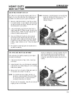
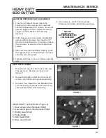
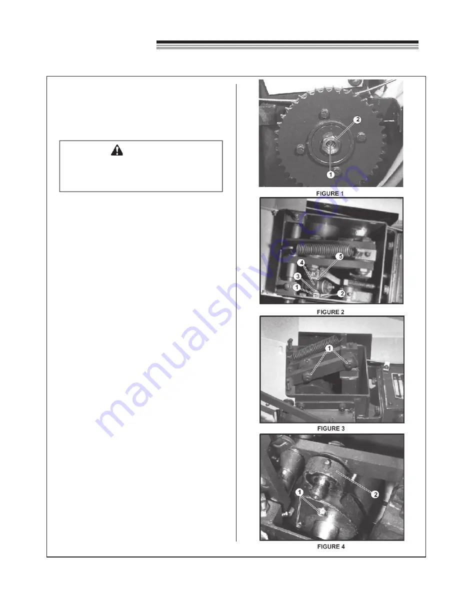
2. From left side of cut-off, remove belt shield
and loosen the locking screw
1
and end bolt
2
. (Figure 1) Remove cut-off drive chain and
finish removing the locking screw and endbolt.
Remove flywheel and clutch lining. If the ball
bearing is worn, remove and replace.
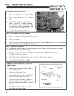
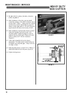
3. From the right side of the cut-off, remove set
screws
1
and brass plugs from the adjusting nut
2
. Remove the adjusting nut
2
, washers
3
, yoke
4
, cam
5
, and thrust bearing. (Figure 2).
4. Remove pressure plate, brake lining, spring and
washer.
NOTE:
If the tie rod is removed from the pressure
plate, Loctite#290 or an equivalent must be applied
to screw threads when reinstalling. Screws should
be torqued to 8 ft-lbs (11 N·m) after reinstallation.
5. Remove springs from trigger and from cut-off ram
assembly.
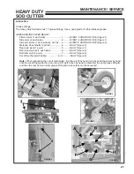
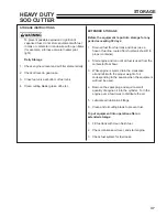
6. Remove the two nuts
1
securing right side
rocker arm. Slide rocker arm out until the arm
can be turned back towards the rear of the unit.
(Figure 3)
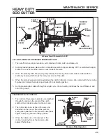
7.
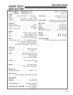
Remove the two screws
1
hold the retainer on
the connecting rod. Remove retainer, seal ring,
and connecting rod
2
. (Figure 4)
WARNING
When tripping the cut-off manually with the
metering wheel, BE SURE to keep hands
and feet away from ALL moving parts.
Summary of Contents for 544853G
Page 2: ......


