HEAVY DUTY
SOD CUTTER
29
SPRING PRESSURE ADJUSTMENT
1. From left side of cut-off, install washers and
spring on tie rod and pressure plate assembly
(replace brake lining if needed). Check the
length of the spring. The length of the spring
must be 4" ± .050" (102mm ±3mm).
NOTE:
If the spring length is not
4"±.050" (102mm
±3mm) the spring MUST be replaced. DO NOT add
washers or shims to make up the difference in the
length of the spring.
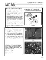
2. Install assembly into cut-off case housing and
push pressure plate (with tie rod) in shaft until
the spring and spacer(s) are inserted as far as
possible.
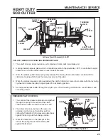
3. Measure the distance from the housing flange
to the brake lining. This dimension should be
7/16"±1/64" (11.11mm±.395mm). (Figure 1)
4. If spring length is correct and the measurement
is not the 7/16" allowed, insert or remove the
appropriate amount of the .030" (.762mm)
spacers (P/N 515200) to obtain the correct
measurement.
5. On right side of unit, install trunnion roller
assembly onto clutch shaft by aligning the timing
marks ("0")
2
. With the "0" on the trunnion roller
1
facing the cam, align the "0" on the roller with
the "0" on the shaft
3
. Slide assembly onto the
clutch shaft (Figure 2).
NOTE:
If the "0" on the shaft is not visible, align the
"0" on the trunnion roller with the first groove to the
right of the keyway on the shaft.
If the timing marks ("0") are not properly aligned, the
cut-off will not operate properly. The timing on the
cut-off revolution will not be correct and will cause
premature and/or erratic cut-off.
6. Install the three spring washers
1
(with convex
side facing the adjusting nut) onto the shaft
(Figure 3).
7. With set screws and brass plugs removed
from adjusting nut, install adjusting nut
2
onto
connecting rod and tighten until pressure plate
and brake lining are tight against housing.
8. Place the "O" ring into position over the thrust
bearing and install the lubrication fitting.
9. On left side of cut-off, install clutch ling, (replace
lining if necessary), flywheel and sprocket.
4” (
±
.050)
SPRING
LENGTH
7/16” (+1/64”)
SPACER(S)
FIGURE 1
2
1
3
2
THE “O” ON SHAFT IS
THE FIRST GROOVE
TO THE RIGHT
OF THE KEYWAY
“O” MUST
FACE CAM
FIGURE 2
1
2
FIGURE 3
MAINTENANCE / SERVICE
Summary of Contents for 544853G
Page 2: ......

