HEAVY DUTY
SOD CUTTER
30
ADJUSTING PRESSURE PLATE CLEARANCE
1. Insert the locking screw partially into the end bolt,
using a lithium based lubricant, or an anti-seize
compound on the threads. Tighten the screw
until hand tight.
NOTE:
If locking screw is not into the end bolt far
enough, the end bolt threads will strip when shim-
ming flywheel.
2. Install end bolt (with locking screw inserted),
washer and shim pack, placing the thicker shims
onto the outside of the end bolt.
3. Tighten end bolt and torque to 75 ft-lbs
(102 N·m). Tighten locking screw.
4. Using a feeler gauge, measure the distance
between flywheel and clutch lining to determine
how many shims to remove to obtain .005"
(.127 mm) clearance. (Figure 1)
NOTE:
The measurement of .005" may vary in
places around the pressure plate. Some places may
read .006" and some may read higher. As long as
the narrowest measurement is .005", installation will
be correct.
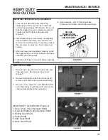
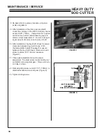
5. If adjustment is necessary, loosen the lock screw
1
in the end bolt
2,
and remove end bolt
2
,
washer
3
and shim pack
4
. (Figure 2)
6. Remove shims as required to obtain the required
.005" (.127mm) between the clutch liner and
flywheel. When replacing shim pack to cut-off,
place a .015" (.381mm) shim to the outside of the
shim pack.
7. After required shim(s) is (are) removed, as-
semble in reverse order of removal. Insert the
locking screw partially into the end bolt using a
lithium based lubricant or anti-seize compound
on the threads. Tighten screw until hand tight.
If the lock screw is not started into the end bolt
properly, the end bolt may strip the threads when
being installed.
8. Tighten end bolt and torque to 75 ft-lbs
(102 N·m). Tighten locking screw.
1
2
3
4
FIGURE 2
MAINTENANCE / SERVICE
Summary of Contents for 544853G
Page 2: ......


