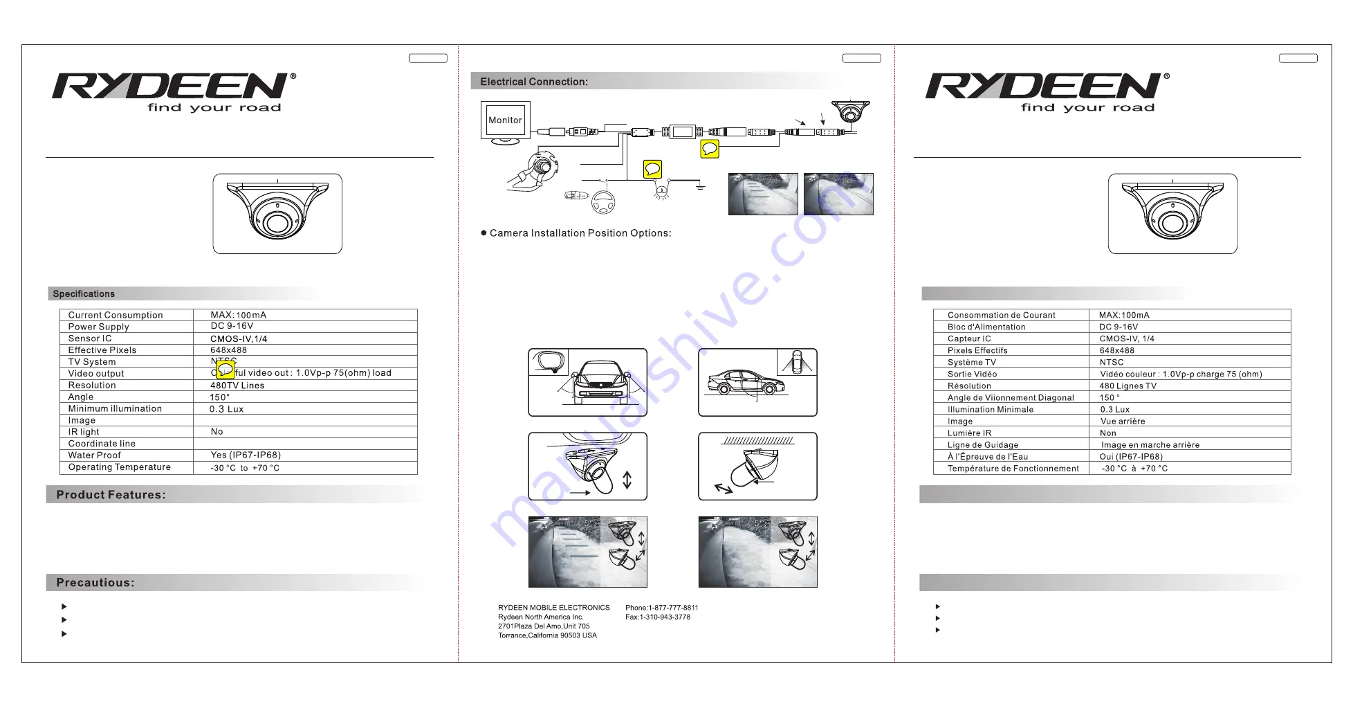
English-1
English-2
French-1
Remove protective lens covering prior to use.
Be cautious when mounting camera and or wiring near fuel tank.
System is designed for +12 volt DC systems only.
1.High Quality C
OS lmage Sensor for High Resolution & Night Time Visibility
2.
3.Automatic Sensitivity Compensation
4.Water Resistant with IP67-IP68 Standard
M
Side View Assist Line ON / OFF Selectable
Side View Camera
Spécifications :
1.Capteur d'Image CMOS de Haute Qualité pour Haute Résolution et Vision Nocturne
2.Sélection d'Image Mirroir / Standard
3.Compensation de Sensibilité Automatique
4.Résistant à l'Eau avec norme IP67-IP68
Caractéristiques du Produit:
Enlever le protecteur de lentilles avant l'utilisation.
Prenez garde lorsque vous installez la caméra et/ou le filage près du réservoir à essence.
Système conçut pour système +12 volts DC seulement.
Mises en Garde:
Caméra de Vision Arrière
Manuel d'Utilisateur
规格:
445.5*210MM
,
120G
双胶纸,双面黑色印刷,成品三折
Owner's Manual
Model
:
Embedded Type CMOS IV Camera
CM-S500
Side View Camera
Model
:
CM-S500
Caméra de Type Intégrée CMOS IV
Side View Camera
Image(3)
Image(1)
Image(4)
Image(2)
Image(5)
Image(6)
Turning Lamp Control Cable (Pink)
Control Box
DVD Screen Control Cable(Blue)
GND (Black)
ACC (Red)
Angle
Adjuster
(Tool)
Angle
Adjuster
(Tool)
Angle
Adjuster
(Tool)
Angle
Adjuster
(Tool)
Right Side View Assist Line
ON/OFF Selectable
Make Solid Connection
To Chassis Ground
3.3V Output
3.3V Input
Camera
Assist Line for Right Side View
Side Back View
1) Locate a flat surface on the bottom edge part of the side mirror. (See Image 1)
2) Remove the mirror
3) Find an open area to feed the wire through the hole.
4) Make sure there is enough wire and no wire loop inside the mirror that can get caught by the motor.
5) Establish connections (ACC, Turn signal, Video RCA and Ground)
6) Power the camera ON and check the monitor for the picture.
7) While looking at the monitor, angle the camera. Recommended angle is 45-60 Degrees from the vehicle (See Image 2)
8) After adjusting, stick the camera under the side mirror.
9) After sticking the camera under the side camera, installer can adjust the actual camera using the supplied "U-Shape" tool.
(See Image 3 & 4)
10) Make sure the guidelines is evenly running down on the side of the car matching ( See Image 5 )
11) Installer should measure what each line represents. Ex: Distance between ORANGE line and RED line
12) Make sure to check all the functions first before assembling the side mirror and panels back.
*
Gridlines can be disabled if it does not match the vehicle's specs
Side View Assist Line Image
Side Back View
Turning Lamp Control Cable (Pink)


