DESCRIPTION OF THE INSTRUMENT
Axio Lab.A1
Control and functional elements on optional components
Carl Zeiss
04/2013 430037-7144-001
41
2.5.2
Microscope stages
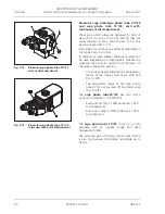
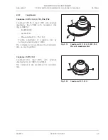
Mechanical stage 75x30 R or L or mechanical
stage 75x30 R ergonomic with stationary drive
Mechanical stage (Fig. 2-14/
7
) for seating,
positioning and securing specimens with
specimen holder.
Specimen holder (Fig.
2-14/
2
) for single-
handed operation or specimen holder for
counting chambers (replaceable after
loosening the two knurled screws,
Fig. 2-14/
1
).
Drive knobs for X (Fig.
2-14/
6
) and Y
adjustment (Fig. 2-14/
5
).
The drive knobs for X and Y can be adjusted
to suit the personal needs of the user, both
in height and friction. The required tools
(Fig. 2-14/
8
) are located in the upper drive
knob.
Vernier scale for display of adjustment
range in X (Fig. 2-14/
3
) and Y direction
(Fig. 2-14/
4
).
Drive knobs on right (R) or left (L) side
depending on model.
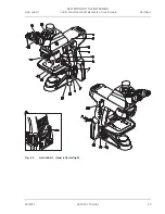
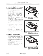
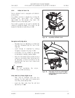
Furthermore, a mechanical stage
(Fig. 2-15/
1
) with ergonomic, stationary X-Y
drive (Fig. 2-15/
2
) is located on the right-
hand side.
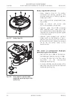
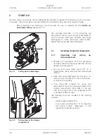
Mechanical stage reflected light 75x30 R
Mechanical stage (Fig. 2-16/
2
) for seating,
positioning and securing specimens with
specimen holding plate (Fig. 2-16/
1
) with
spring clips.
Drive knobs for X and Y adjustment on right-
hand side.
Vernier scale for display of adjustment range
in X and Y direction.
Removable specimen holding plate (after
loosening the two knurled screws).
Fig. 2-14
Mechanical stage 75x30 R with
specimen holder
Fig. 2-15
Mechanical stage 75x30 R
ergonomic with stationary drive
Fig. 2-16
Mechanical stage reflected light
75x30 R with specimen holding
plate

