START-UP
Axio Lab.A1
Installing standard components
Carl Zeiss
04/2013 430037-7144-001
61
3.1.12
Installing or replacing LED modules
Axio Lab.A1 transmitted/reflected light stands may
be equipped for transmitted light applications with
a 35 W halogen lamp or an 3 W LED lamp (see
Section 3.1.10) and for reflected light fluoresce
applications with up to two LED modules from the
delivery program (see also Section 2.2). To insert or
replace LED modules, proceed as follows:
x
Switch off the microscope, disconnect the
power cord.
x
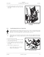
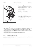
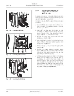
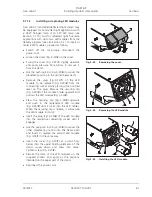
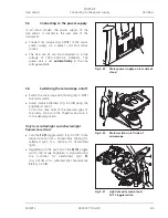
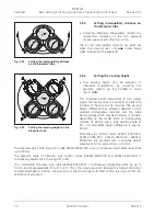
Loosen the screw (Fig. 3-23/
2
) in the cover.
x
Swing the cover (Fig. 3-23/
1
) slightly upwards
and apply pressure from below to remove it
from the stand.
x
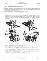
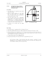
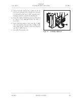
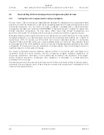
Use the push-pull rod (Fig. 3-24/
4
) to swivel the
placement position in the center (beam path).
x
Remove the plug (Fig.
3-24/
1
) of the LED
module to be replaced (Fig. 3-24/
2
) from the
connecting socket while pressing the notched
lever on the plug. Remove the securing clip
(Fig. 3-24/
3
) of the module holder upwards and
pull out the LED module (Fig. 3-24/
2
).
x
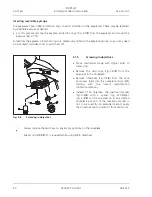
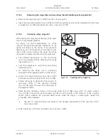
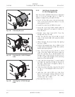
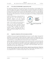
Press the securing clip (Fig. 3-25/
5
) upwards
and push in the replacement LED module
(Fig. 3-25/
3
) until it locks into the LED holder.
When the securing clip is release, it will secure
the LED module in its slot.
x
Insert the plug (Fig. 3-25/
2
) of the LED module
into the respective connecting socket until it
engages.
x
Use the pull-push rod (Fig. 3-24/
4
) to swivel the
other placement position into the beam path
and insert or replace the second LED module
(Fig. 3-25/
1
) in the same way.
x
Insert the cover (Fig. 3-23/
1
) at a slant from
below into the upper holding elements of the
stand, swivel down and press into place.
Tighten screw (Fig. 3-23/
2
).
x
Record the data of the LED modules on the
supplied stickers and apply at the positions
intended on the upper part of the stand.
x
Reconnect the power cord.
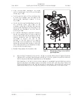
Fig. 3-23
Removing the cover
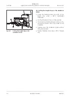
Fig. 3-24
Removing the LED module
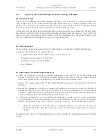
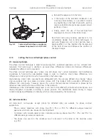
Fig. 3-25
Installing the LED module

