OPERATION
Axio Lab.A1
Lighting and contrasting method in transmitted light
Carl Zeiss
04/2013 430037-7144-001
85
4.1.4.5
Circular polarization contrast
(1) Application
Unlike standard polarization contrast, circular polarization contrast does not show any dark (extinction)
positions that depend on the angle of rotation (azimuth) of the specimen relative to polarizer or analyzer.
This means that when the stage is rotated the same image impression remains, as the light/dark positions
are omitted. With optical anisotropy, all transparent specimens display the characteristic interference
colors.
(2) Instrumentation
Tension-free objectives
Rotary stage Pol
Circular polarizer D (no polarizers may be adapted on the condenser) including corresponding
O
/4 plate.
Stationery analyzer slide D or screw-in analyzer (in Axio Lab.A1 tubes).
(3) Setting the microscope
x
Set the microscope as in the transmitted light brightfield according to KÖHLER (see Section 4.1.1).
x
Center rotary stage Pol or objective (if this has not already been done – see Section 3.1.8.5 or 3.1.8.6).
x
Initially do
not
use a specimen for the further settings.
x
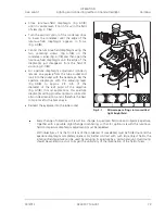
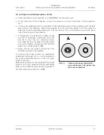
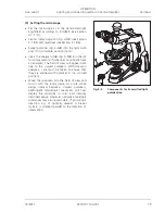
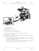
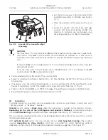
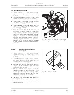
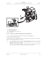
Swivel in the lower part of circular polarizer D (Fig. 4-9/
2
) into the beam path until it engages and
evaluate the extinction (darkening) of the field of view without the specimen at full light intensity.
If this is not optimum, align the analyzer in the tube or intermediate plate as necessary.
x
Insert the respective slide 6x20 with
O
/4 plate (Fig. 4-9/
1
) as far as it will go into the slot for
compensators above the nosepiece.
x
Then swivel the upper part of circular polarizer D (Fig. 4-9/
4
) into the beam path.
x
Rotate the lever of the
O
/4 plate of the circular polarizer D (Fig. 4-9/
3
) until the extinction is maximum
(dark-gray field of view) (lever points 45° to the right).

