OPERATION
Axio Lab.A1
Lighting and contrasting method in transmitted light
Carl Zeiss
04/2013 430037-7144-001
89
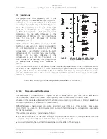
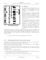
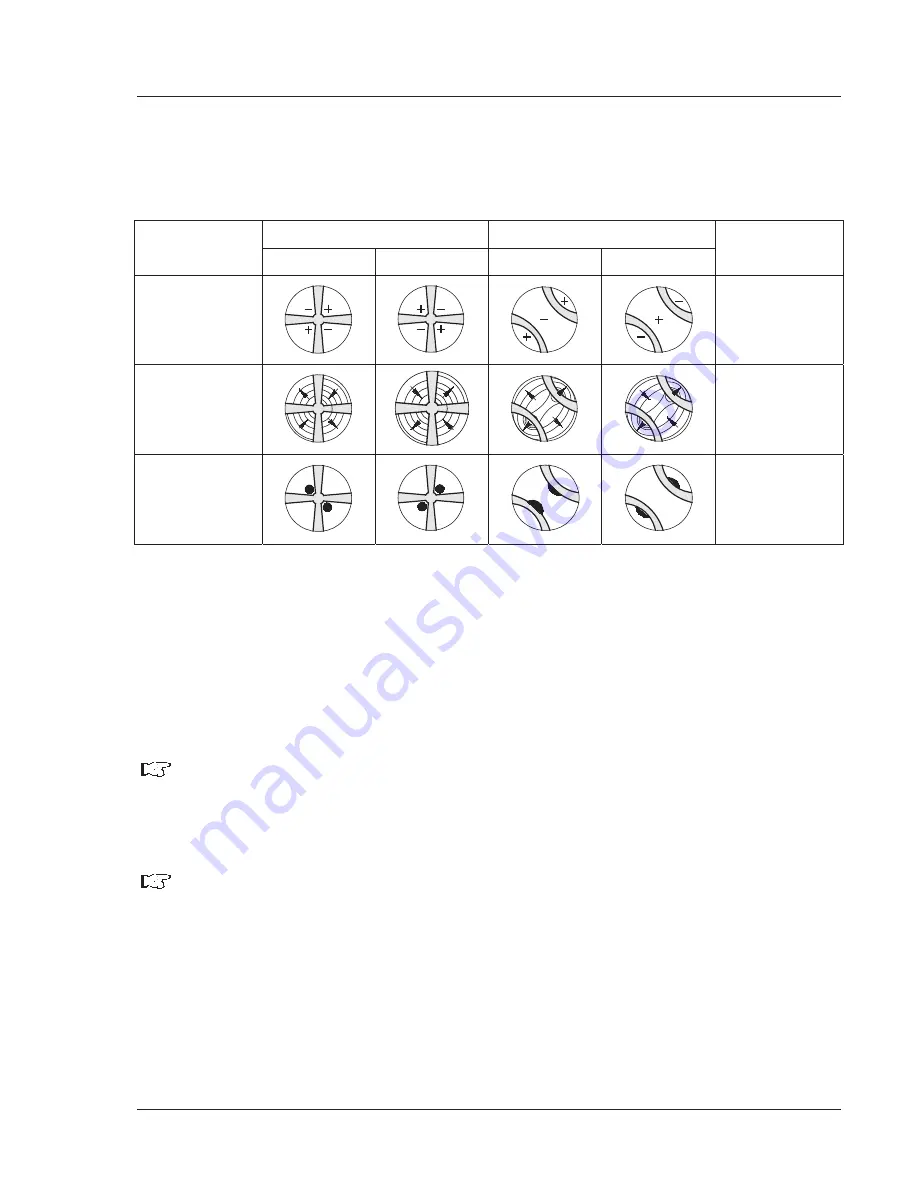
Inserting a compensator
O
(473704-0000-000) or
O
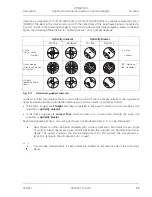
/4 (473714-0000-000) or a wedge compensator 0-4
O
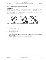
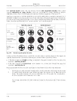
(000000-1140-663) in the compensator slot with the initial state of the axial figure being as illustrated in
Fig. 4-11 results in the following changes in color shown schematically (blue and yellow areas) to the axial
figure, thus allowing differentiation in "optically positive" and "optically negative".
Optically uniaxial
Optically biaxial
Positive Negative Positive Negative
O
-Plate
(white
o
blue
o
yellow)
+ = blue
– = yellow
Quartz wedge
(Direction of motion
at insertion)
Ò
Direction of
Ó
movement
O
/4 plate
(position of black
spots)
Fig. 4-11
Determining optical character
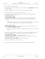
In the case of less favourable sections in which the cross-hair center is optically uniaxial or the isogyres are
optically biaxial specimens outside the objective pupil, an assessment is possible as follows:
x
If the black isogyres are
straight
and they run parallel to the pupil (in relation to the cross-hairs), the
specimen is
optically uniaxial
.
x
If the black isogyres are
curved lines
which wander on a circular path through the pupil, the
specimen is
optically biaxial
.
Paying appropriate attention, also such axial figures not illustrated in Fig. 4-11 can be interpreted.
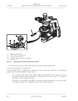
Axial figures can often be better displayed with circular polarization. Particularly the axis angle
of optically biaxial specimens (quasi distance between the isogyres) can be determined more
clearly. The optical character can also be determined. For this purpose the compensator
O
(6 x 20), arranged in the compensator slot, is used.
Two storage compartments for 6x20 slides are located on the reverse side of the conoscopy
stand.

