OPERATION
Axio Lab.A1
Lighting and contrasting method in transmitted light
Carl Zeiss
04/2013 430037-7144-001
91
(3) Setting the microscope
x
Set the microscope as in the transmitted light
brightfield according to KÖHLER (see Section
4.1.1 (3)).
x
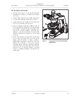
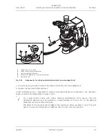
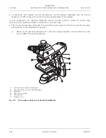
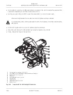
Center rotary stage Pol (Fig. 4-12/
1
) (see Section
3.1.8.5) and objectives (see Section 3.1.8.6).
x
Swivel polarizer (Fig. 4-12/
3
) into the light path
and, if it is rotatable, position it at 0°.
x
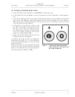
Swivel the analyzer into the beam path and
adjust on the setting wheel until the field of
view is dark.(Fig. 4-12/
2
)
x
Move the specimen into the field of view and
turn it with the rotary stage. As a rule, while
being rotated between crossed polarizers,
birefringent (anisotropic) specimens will now
display the variations in color and intensity
described above. However, optically anisotropic
substances may also remain dark, if an isotropic
direction, e.g. of optically uniaxial or biaxial
crystals, is oriented parallel to the direction of
observation.
4.1.6.2
Determination of gout and
pseudogout
x
Set the microscope as in the transmitted light
brightfield according to KÖHLER (see Section
4.1.1 (3)).
x
Swivel the polarizer, rigidly fixed or rotatable
(Fig. 4-12/
3
) into the beam path. Set the
rotatable polarizer to the 0° position.
x
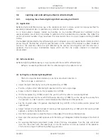
With the Axio Lab for polarization push the
analyzer (453681-0000-000) into the 6x20
slider mount. (Fig. 4-12/
2
)
x
With the AxioLab for conoscopy swivel the
analyzer into the beam path and bring it into a
crossed position using the setting wheel.
Additionally, insert compensator 6x20 (473704-
0000-000) into the slider mount 6x20.
x
The field of view will appear dark due to the
crossed polarizers.
x
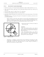
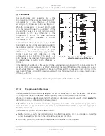
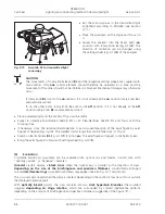
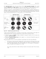
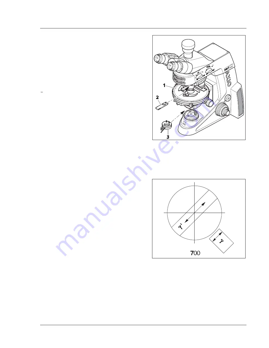
Select crystals which are oriented in the gamma
direction (Fig. 4-13).
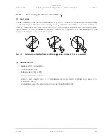
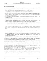
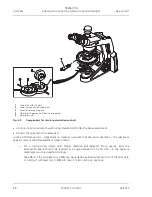
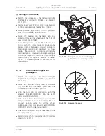
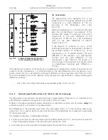
Fig. 4-12
Components for transmitted light
polarization on conoscopy stand
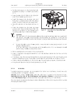
Fig. 4-13
Gamma direction

